The Rickety 3D Printer
A 3D printer built from scratch in the labs of Texas Inventionworks.
The Rickety 3D Printer was my final lab submission for EE 445L Embedded Systems Lab, one of my favorite classes at UT. It is result of three months of very dedicated work, lots of support from others, and more than a few mishaps. Ultimately, this project submission came in 2nd for the UT ECE Embedded Systems competition, earning just over half of all possible points and getting me out of taking my final.
Background
During my last year of my UT undergrad I took EE 445L Embedded Systems Lab, considered by many students to be one of the most challenging undergraduate ECE classes. Throughout the semester we were to complete 11 labs, the final lab being of our own design. Throughout the semester we would begin to design and build our final labs. Each team of students would submit their final project to the competition, and the top three projects would be exempt from taking the final exam. For a class as tough as this, the award was a powerful incentive.
Texas Inventionworks
I was fortunate to have a few advantages in this project. First, I was a part-time employee at Texas Inventionworks (TIW), the makerspace for engineering students at UT. This place is magic. Chock-full of interesting machines, interesting ideas, and interesting people. And I happened to be familiar with many of these interesting machines, ideas, and people through my time working at TIW.
When the opportunity arose to come up with our own project, I went straight to my colleagues and friends at TIW asking for advice. One of the leaders, Steve, offered a great idea. There were some linear rails, belts, and stepper motors left over from a previous project. He offered to let me use those to build a 3D printer if I would mention TIW and generate some excitement for the space.
Wonderful! A win-win for everyone. I could get some parts and a desk in the electronics lab, and all I had to do was hype my favorite place at UT. Easy. Now the hard part.
Approach
Turns out, this project was actually three projects in a trench coat, each depending on the former. In the stack:
- The case: The case is the part most people imagine when they hear “3D Printer”. It is all of the hardware that makes the machine: linear rails, belts, motors, lights, the printing bed, end stops, etc. I needed to turn our loose box of parts into a case.
- The control board: Once the case is complete, we have a fully built box that does not do anything. The control board acts as the orchestrator, converting commands into coordinated movements and actions. Everything from the movement of motors, extrusion of filament, to the heating of the bed and filament heating elements are performed by the control board.
- The GCode Sender: With both a case and a control board, the machine can now take commands and convert them into intricate actions. These commands come from our GCode sender. It is responsible for ensuring commands are received and executed in a timely manner, and handles unexpected events.
If you have never worked with 3D printers before, this may seem confusing. I always love a good analogy, so I will try to devise one for you here.
Imagine this whole system as a car. The case is the visible parts: the wheels, the engine, the frame. Very good, but it won’t drive anywhere quite yet. In order to move, it will need a way of converting commands into actions.
The control board is like our steering wheel, pedals, indicator blinker buttons, and windshield wiper stick. Of course, the gas pedal does not make the car move. It just converts a command (depression of the gas pedal) into actions (more engine force). The car is now drivable!
Finally, our GCode sender is like the driver. Its job is to interpret the state of the environment and convert its plans into commands. If it wants to reach a higher speed, it will send a command for more gas.
The Case
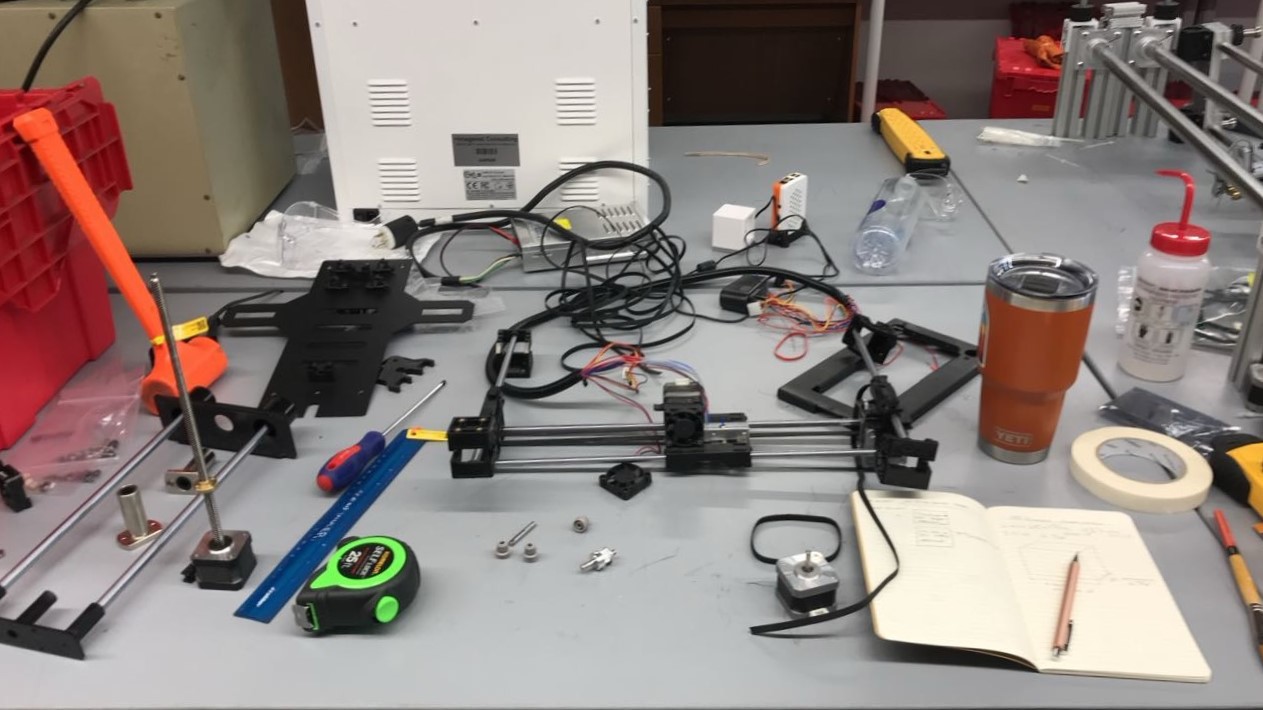
First, we need our case. All the commands in the world will not do us any good if there is nothing to perform them. My job was to take the loose parts and assemble them into a machine.
Now, although this step involved the least electrical engineering, I think it is still exciting to talk about. Being now several years removed from my undergraduate, I still marvel at the fact that it was possible to build a machine using the machines at Texas Inventionworks. I will be forever grateful for that opportunity.
Cutting the Case
So what’s the plan? I measured out the linear rails and base to understand the inside dimensions that I would need for the case. A 3D printer is, in most cases, just a box with mounts for motors and the bed. TIW had multiple Spectrum laser beds, good for quickly cutting thin sheets of wood and acrylic with high precision. I could use these to design and fabricate the exterior of the case quickly.
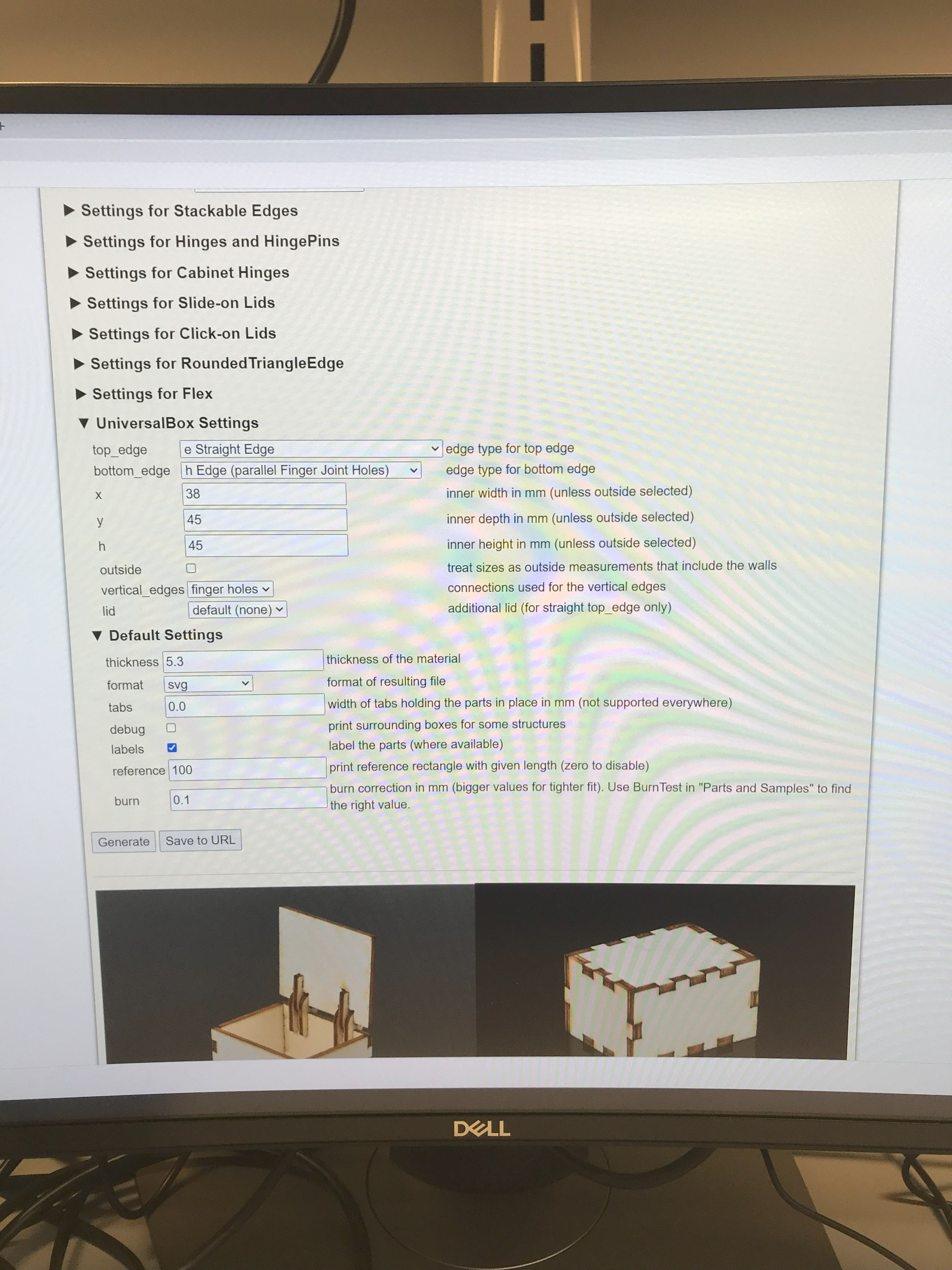
So I went to a favorite site of TIW, boxes.py, to build a box to the correct dimensions. If you ever find yourself needing to laser cut a 3D project, you ought to check it out. It will save you an enormous amount of stress designing your projects, and will even plan your finger joints to boot.
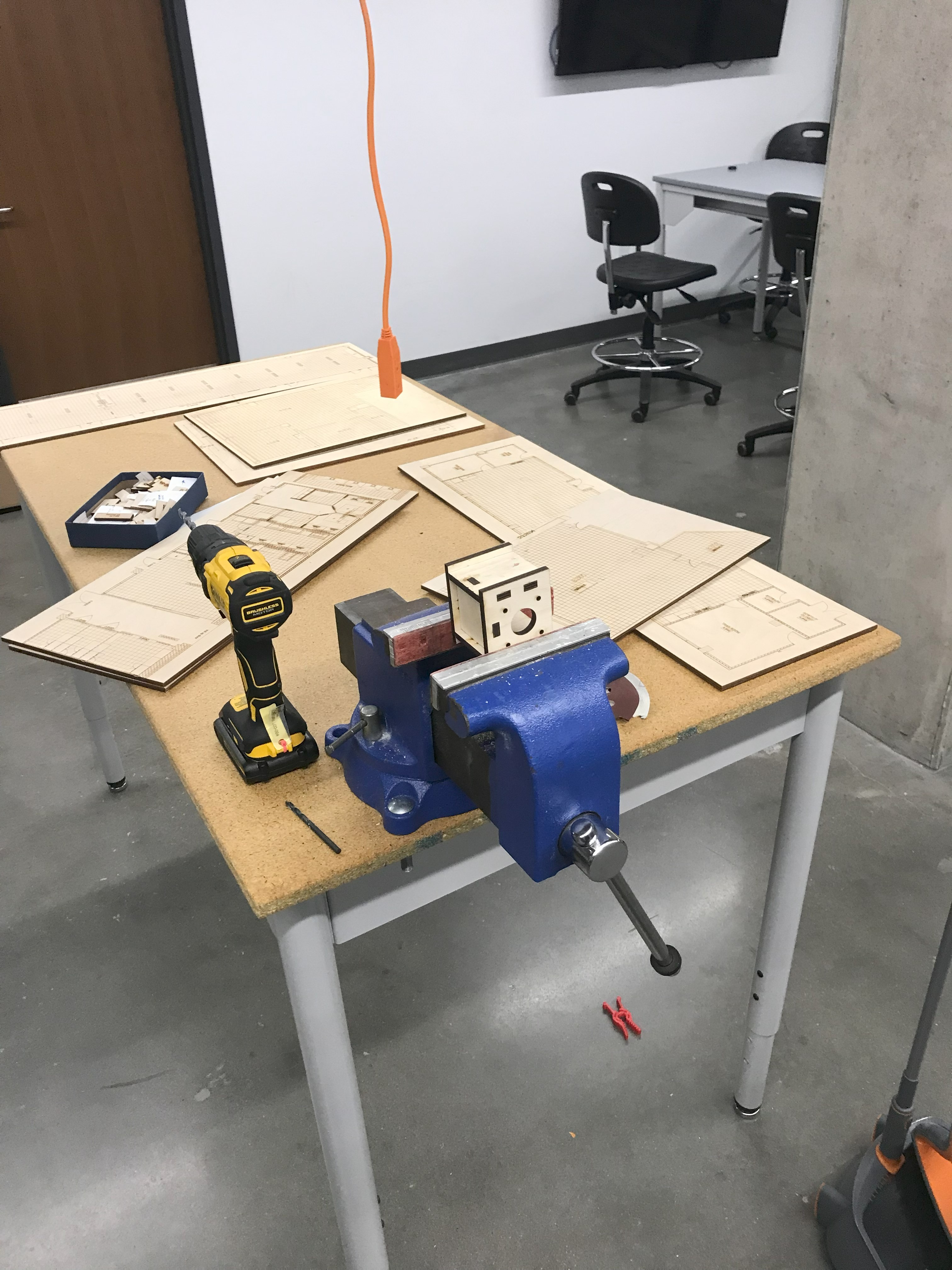
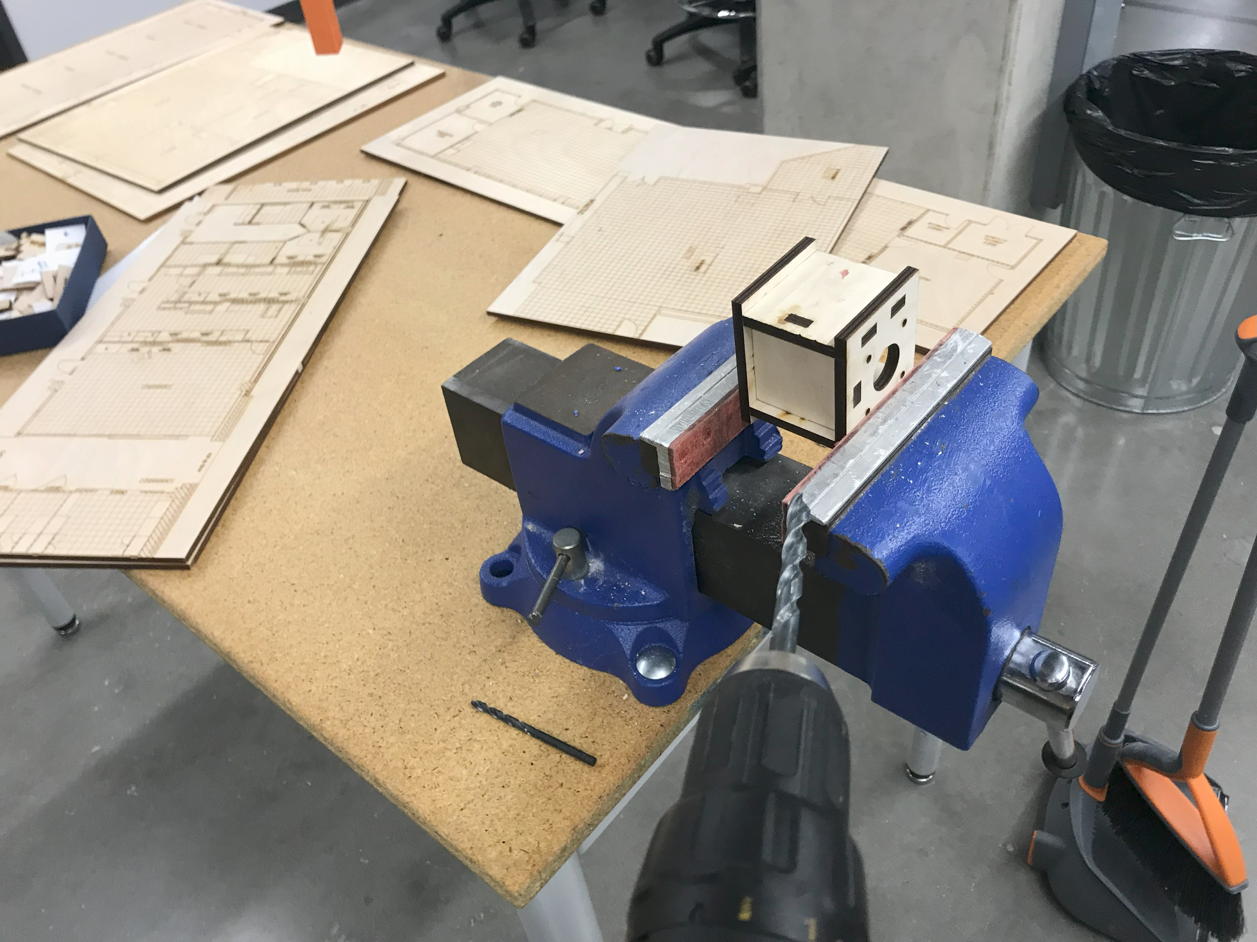
Center and Right: Drilling mounting holes after laser cutting the parts.
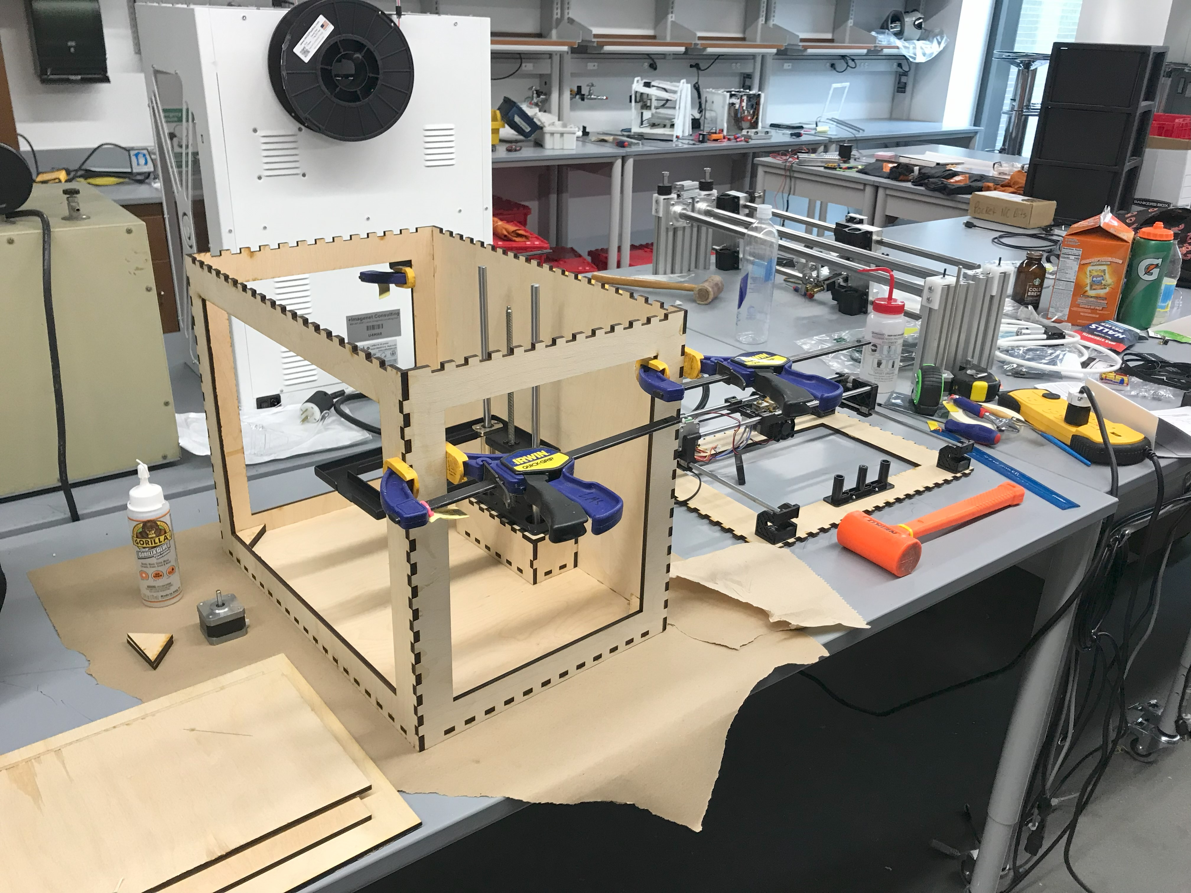
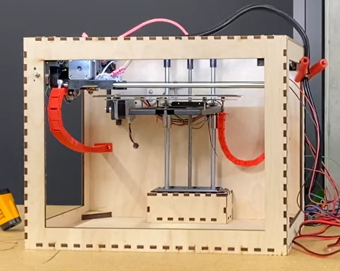
After cutting the outer case from 1/4 inch plywood, I cut a large window in four of the six faces to access the inside. You can see that our vertical rails fit snugly inside. What a relief! The finger joints holding the faces together were very snug, and held together easily. With a little wood glue and some clamps, the case ended up being surprisingly sturdy.
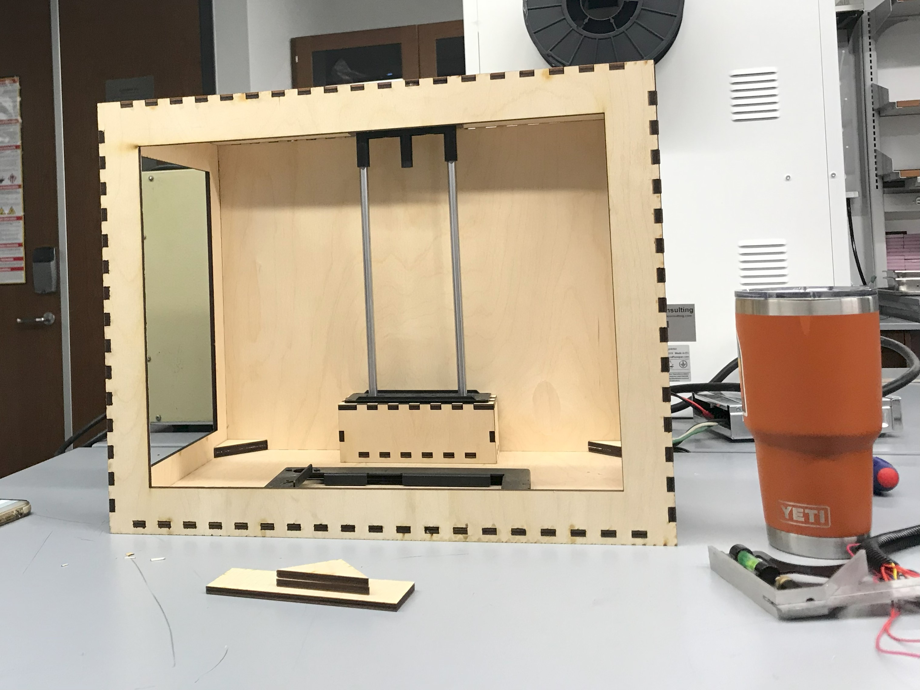
Testing the Hardware
Last but not least, we needed some internals. All of the parts fit in the case, but do they work? I borrowed a pre-built control board and a power supply to test the hardware.
The Control Board
This component is what made this an embedded systems project, and was the heart of the lab. The control board receives signals from a gcode sender and maps those to discrete actions. For this project the control board managed:
- 6 motor drivers
- 3 for moving in the X,Y, and Z axes
- 3 for filament extrusion
- 4 fans
- 3 for cooling print heads
- 1 fan for cooling the case
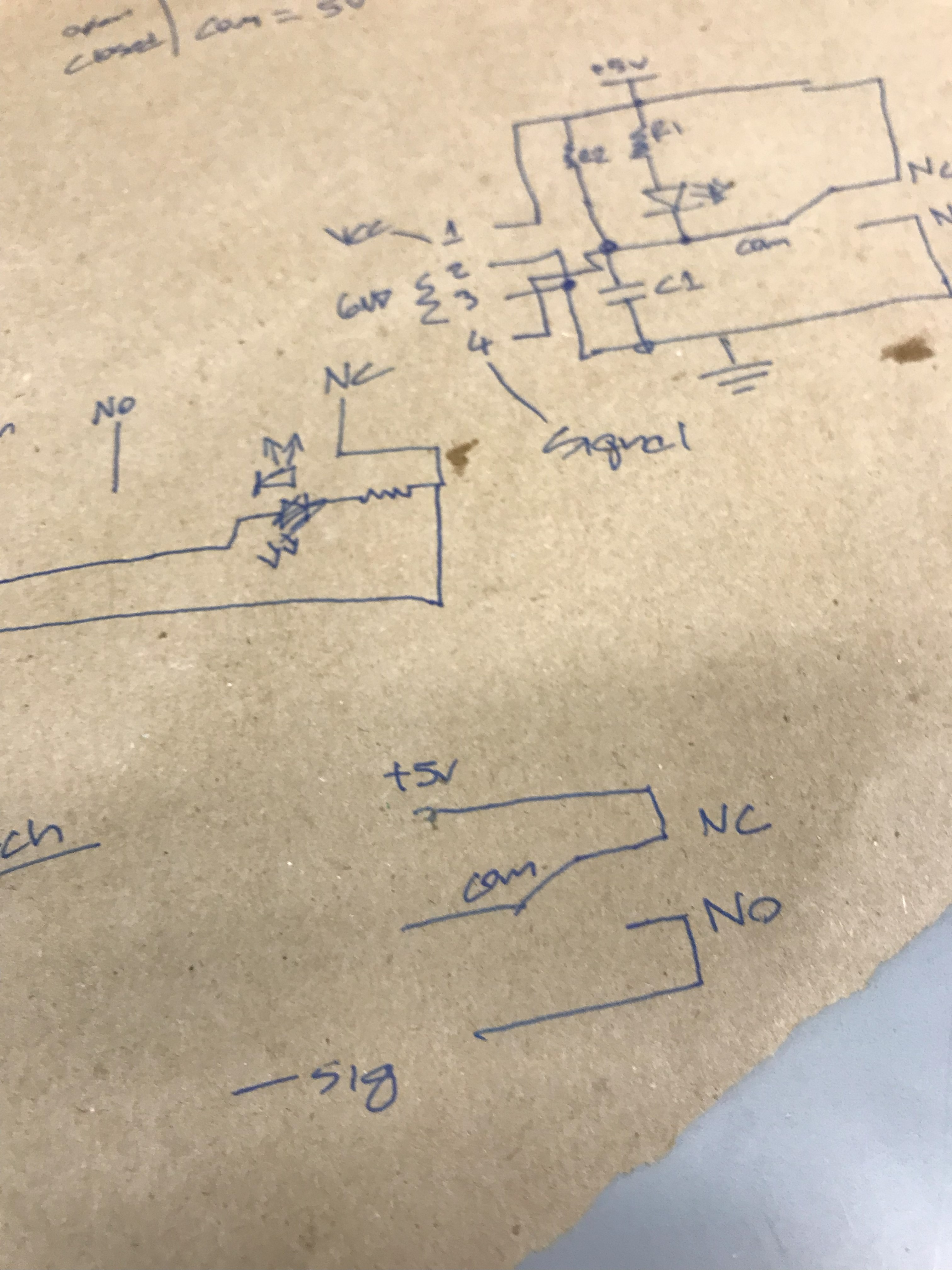
- 3 endstops for calibrating the position of the print head
- 1 heated print bed
- 3 thermistors for measuring the temperature of the heated bed and print head
- 1 strip of case LEDs
That turns out to be a lot of parts, and a precarious mix of high power lines and low power signals all on one board.
System Design
Before designing a control board, I needed to decide which components the board needed to control. The first few decisions are relatively easy. We will need it to move in three axes. The extruder will need to be hot so that it can melt the filament before depositing it on the print bed. The print bed ought to be hot, but not too hot, to prevent the print from warping as it cooled.
But then there are some unexpected parts that you might only recognize if you are familiar with 3D printers. Or, more precisely, if you are familiar with the many, many ways in which they can go wrong. With enough failed prints, you would ask:
- How can I ensure the motor that is driving the filament through the heated tip does not itself overheat?
- A: An extruder fan
- How can I shut this down immediately if something goes bad?
- A: Emergency power switch
- How does a 3D printer “know” where the print head is?
- A: Using endstops to calibrate for the origin
- How can I see my cool print better while it is printing?
- A: LEDs in your case
- Who is in charge of commands for our actuators?
- A: The MCU, with control firmware
The firmware in this last point has a huge job. It turns out, almost all of our devices required different protocols to get them to work as intended, and many at different frequencies. In addition, there were lots of possible safety concerns for this project, from thermal runaway to power loss recovery. Not surprisingly, the firmware to manage all of these parts in near realtime is very complex, and I was not going to have time to write this by the end of the semester.
After reading around I found Marlin, an open-source firmware suite that was designed for running on 3D printer control boards. Even better, it was compatible with my favorite microcontroller board at the time, the NodeMCU ESP32. Lovely! Now to connect the parts.
Schematic Design
For the embedded systems lab class, we were supposed to use Eagle EDA to design our boards. At the time, I did not have a laptop that I could easily carry with me to class. My daily driver while on the move was a 2017 Chromebook 3, which did not support this, or really any software.
Luckily, I had a very kind TA who let me use EasyEDA, which has a convenient web interface. Bonus points that it connects natively with JLC PCB, making fabrication a breeze. Thanks, Burak.
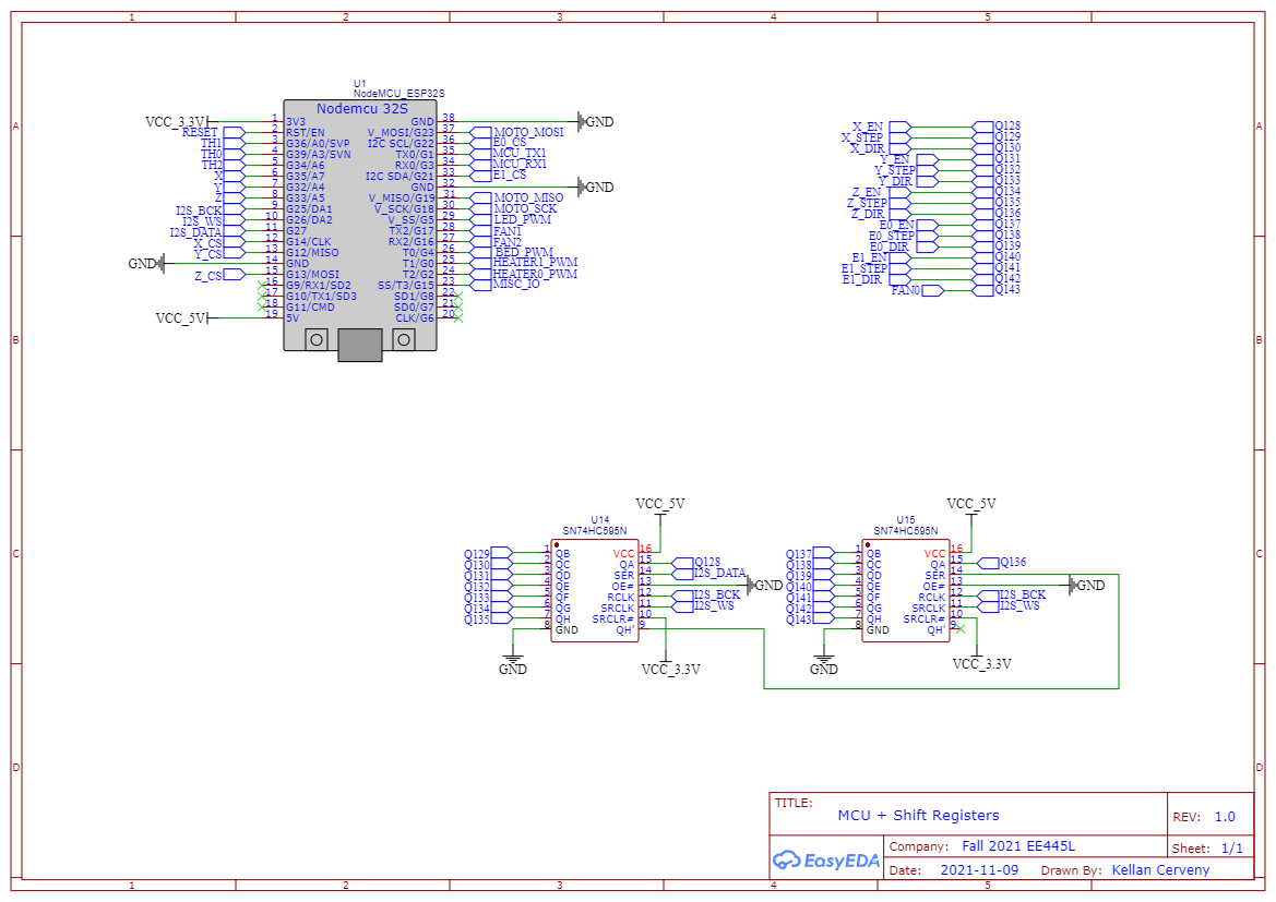
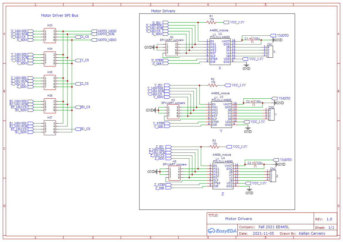
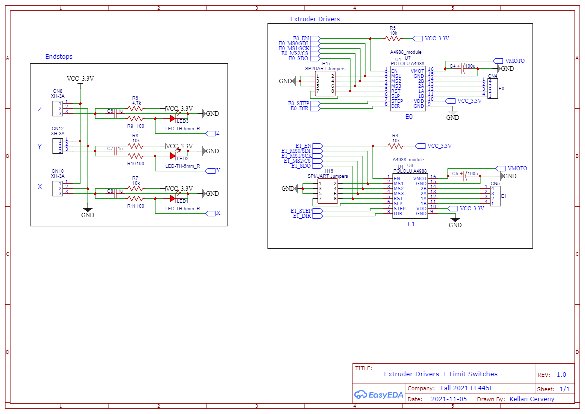
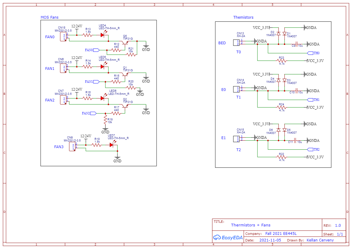
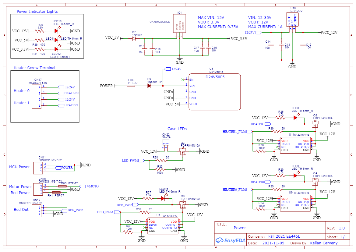
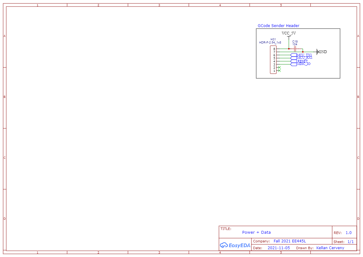
A seasoned electrical engineer may find it surprising how simple many of the sub-components ended up being. With the exception of a few niche parts and poorly-named headers, most of these diagrams will be instantly recognizable. They will be further surprised with what a mess I made of these neat diagrams once I placed and router them on the PCB.
Probably the only part worth discussing is found in schematic 1 on the first slide. To interface with all of these components required far more pins than the NodeMCU could support with a measly 38 pins. Indeed, Marlin firmware was originally written for the STM32 MCU family, which often have 64 pins. I used two I2C shift registers with to extend the number of available GPIO pins, at the expense of speed. Fortunately, the NodeMCU board boasts a clock speed of over 160 MHz, where a typical STM32 board is run at only 16MHz. This leaves plenty of overhead despite losing some time to the shift registers.
PCB Design
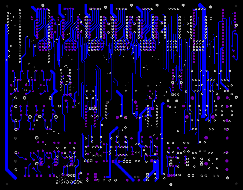
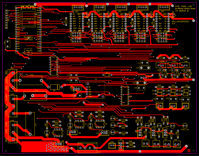
Slide the divider back and forth to compare.
This board was fun to route. I followed the pattern of having each side of the board correspond to an axis of travel for traces. The top was for left-right traversal, and the bottom of the board was top-bottom. If I were to do this again, I may have used more layers to act as ground planes for the high-power components, but we were limited to 2 layers at the time.
Most of the high-power traces were concentrated in the bottom left quadrant of the board. These were to offer three (3!) power inputs for the bed, the motors, and for the low-power components separately. There were also the header and power transistor used to manage the print bed heating via PWM.
Once this was ready, it was just a matter of clipping the correct parts into place and letting it run.
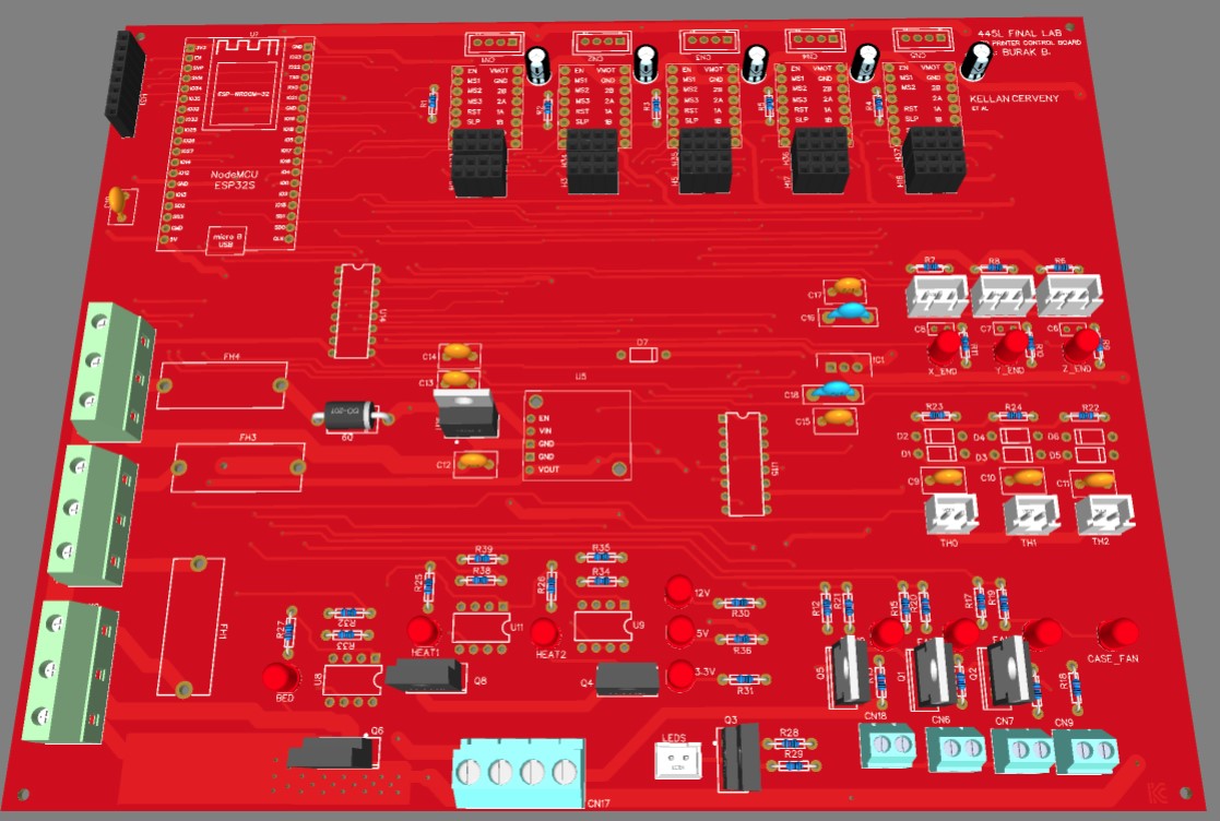
PCB Testing
The GCode Sender
GCode Hardware
The GCode sender was just the opposite of the control board: simple hardware and challenging firmware. The system was tiny: an MCU, a dial, a button, and some pins to connect to the control board. After checking the setup on a breadboard to make sure it worked, the system was easy to consolidate on a PCB.
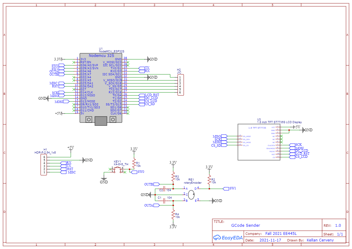
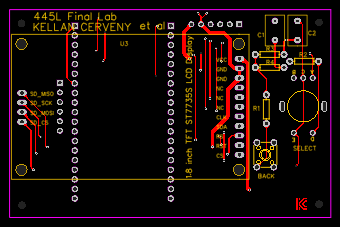
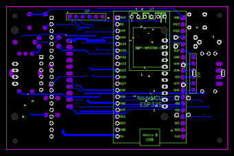
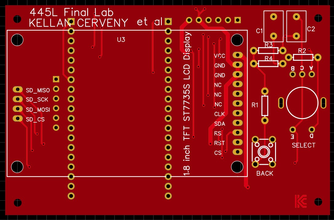
The LCD display I selected also had a micro SD card slot, making it easy to store and transfer large files to the gcode sender. As will be seen in the firmware section, the SD card could also be used as storage for the files uploaded via the internet.
GCode Sender Firmware
This is where I really dove deep with the firmware. Again the MCU for this device was the Espressif ESP32, renowned for its speed, price, and built-in networking capabilities. I used the Arduino IDE to compile and flash the firmware for this device, as it was a more mature platform for ESP libraries at the time. All of the code written for the gcode sender was written in the Arduino language, which is simply a slightly modified C++.
The firmware for this component served multiple functions at once.
- Send and receive GCode, managing the print. This is the device’s primary job. Send instructions to the control board one at a time, and respond appropriately to any messages it returns.
- Act as an interface for the user. The user should be able to see the relative progress of the print and other important data, such as the current temperatures of the extruder and the print bed. This data is received from the control board, which is managing those components.
- Host a web server? This one was not at all necessary, but made the project a lot more fun. I thought it would be neat if a user could access the gcode sender via their browser and upload files for prints they wanted to complete. Of course, they could always write it to the micro SD card and insert it in the display. But this saved a little bit of walking, and allowed for my classmates to submit their fun prints, too.
Conclusion

Project Video
As a part of the grade for submitting the final lab, each project needed to submit a video describing the components and its functionality. Check it out to see the printer in action! You can also catch a glimpse of the magic inside of Texas Inventionworks.