Hacked Garage Opener
Sometimes you gotta break in to your own home
Problem
In college I lived in an apartment with a garage in the basement where I parked my car. The garage door was opened with a fairly generic looking opener. Unfortunately for me, I lost mine one day. This was a big problem. How was I going to get back in my garage?
My hope was that I could go purchase a replacement and reprogram it to open the door. So I went on Amazon and got myself a 2 pack of the exact same opener that I had just lost.
Reverse Engineering
So I had an opener. But how was I going to reprogram it? Of course, the first thing I had to do was crack it open to see what was going on inside.
On the outside of the remote there was some text that said “FCC ID: SU7318LIPW2KC”. I knew this device was an intentional transmitter, so it would have to registered with the Federal Communications Commission to ensure it would not interfere with other devices. I looked up the device on the public database to see if I could find any more information about the board.
Sure enough, we got a hit. And there was an astounding amount of information available about the board. The user manual indicated that the transmitter operated at the ISM band of 318MHz, and also indicated that it used a Weigand 26 bit output. I also checked out the images of the PCB to ensure that these were the same transmitters.
Already this is a lot of information. The reports have told us on which band to listen, and what to expect when we do. The next step is to hear what the transmitter has to say.
RF Sniffing
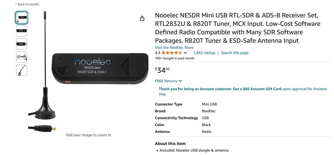
Most people are familiar with the idea of tuning a radio to different frequencies to listening to different music stations in their car. But can this be done for other frequencies outside of the normal radio band? Absolutely, but not with a normal radio. I picked up a software-defined radio that could pick up signals from 27MHz-1700MHz, plenty of range to hear the button’s 318MHz signal.
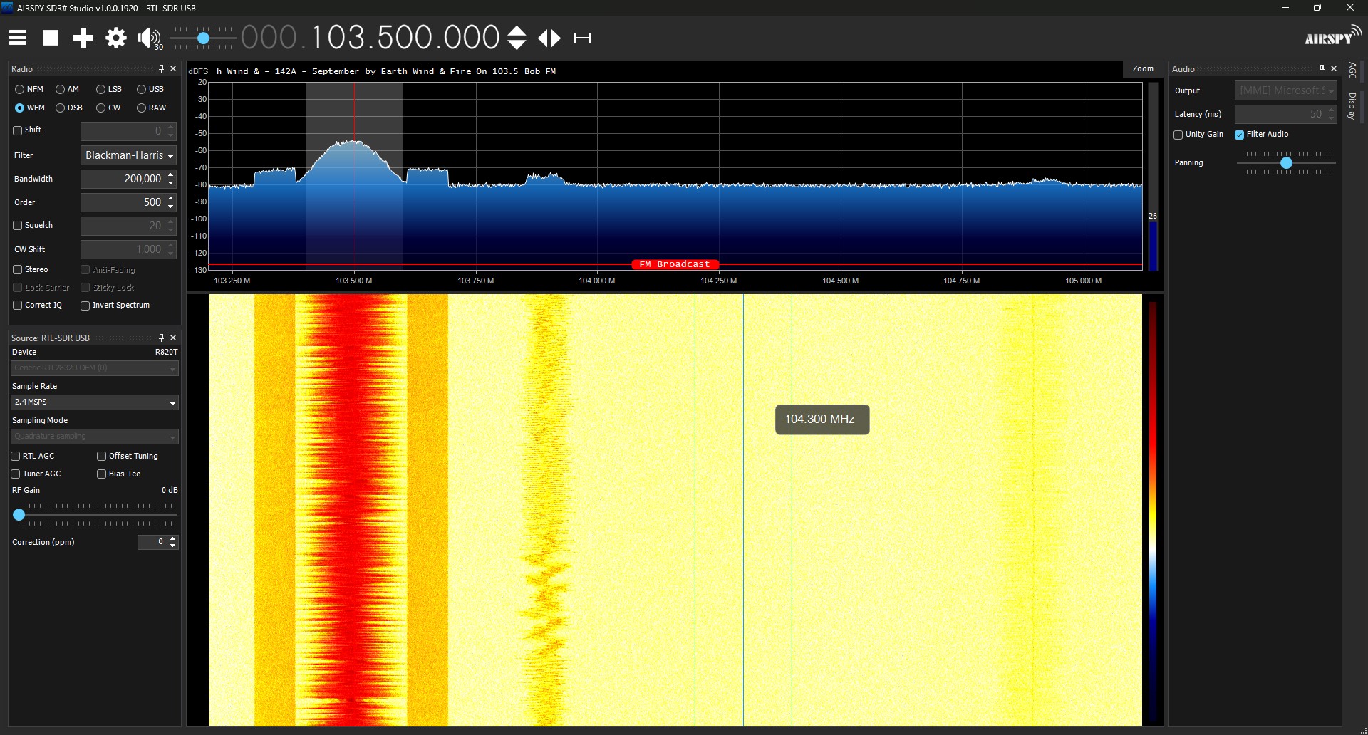
To make the software defined radio (SDR) work, I installed and configured AirSpy SDR#. This tool allows a user to tune their radio to pick up different frequencies across its capable band, including normal radio stations. I tuned the SDR to 318MHz in AirSpy and pressed the button on the garage transmitter. Shockingly, the receiver was able to pick up the signal no problem!
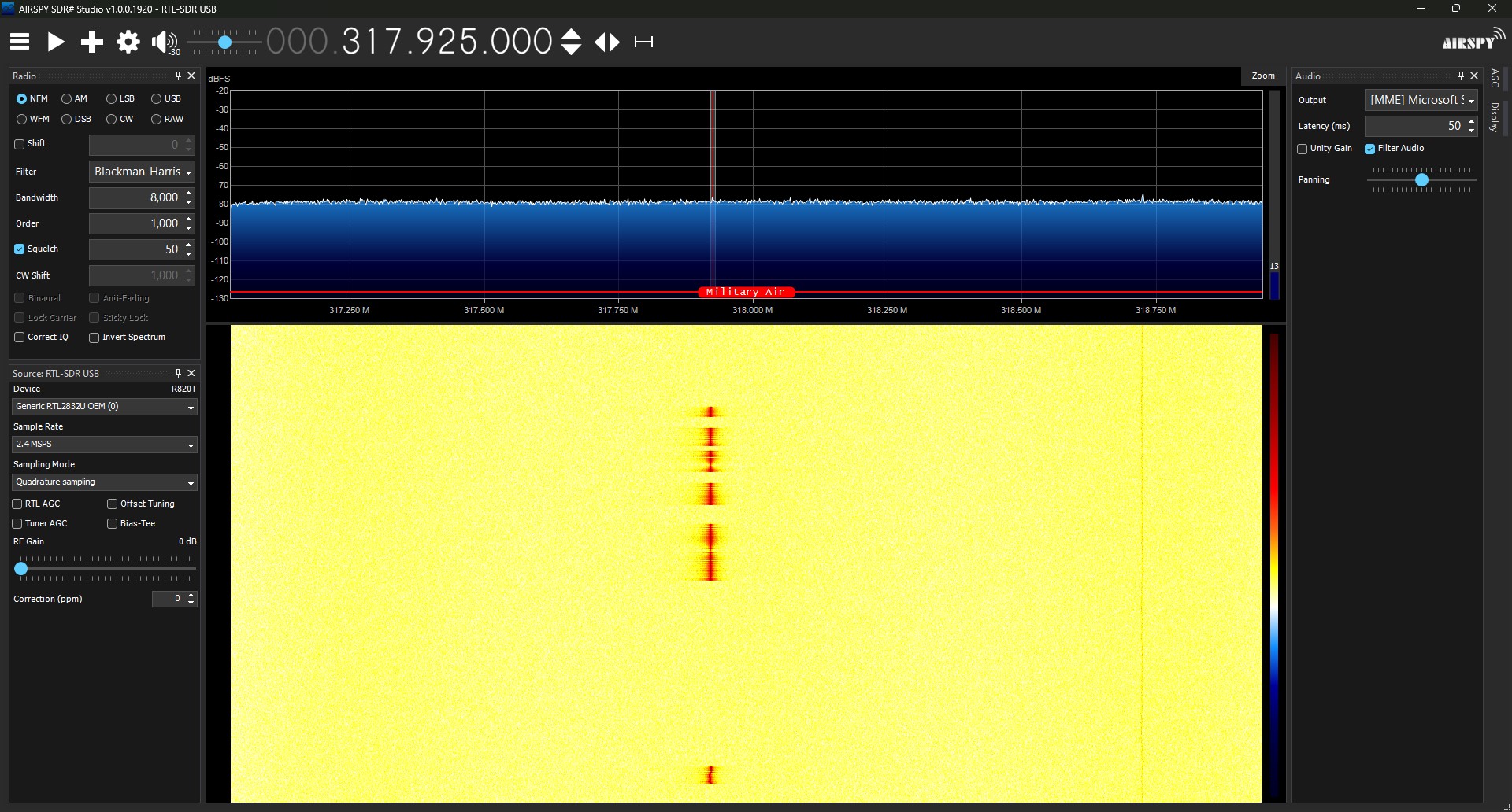
Now to dig a little deeper. By tuning the contrast, speed, and offset of the receiver, I was able to get a better picture of the actual signal. With the enhanced view, you can see that there appears to be a pattern in the signal being sent by the garage button.
My hunch was that it is likely the garage open signal being sent multiple times in a row. If this is true, that would mean that the key fob is sending the same signal on each press of the button. If I could capture the signal from a programmed button to my garage like this, interpret it, and send it myself, I could then get back in my apartment’s garage.
The Replay Attack
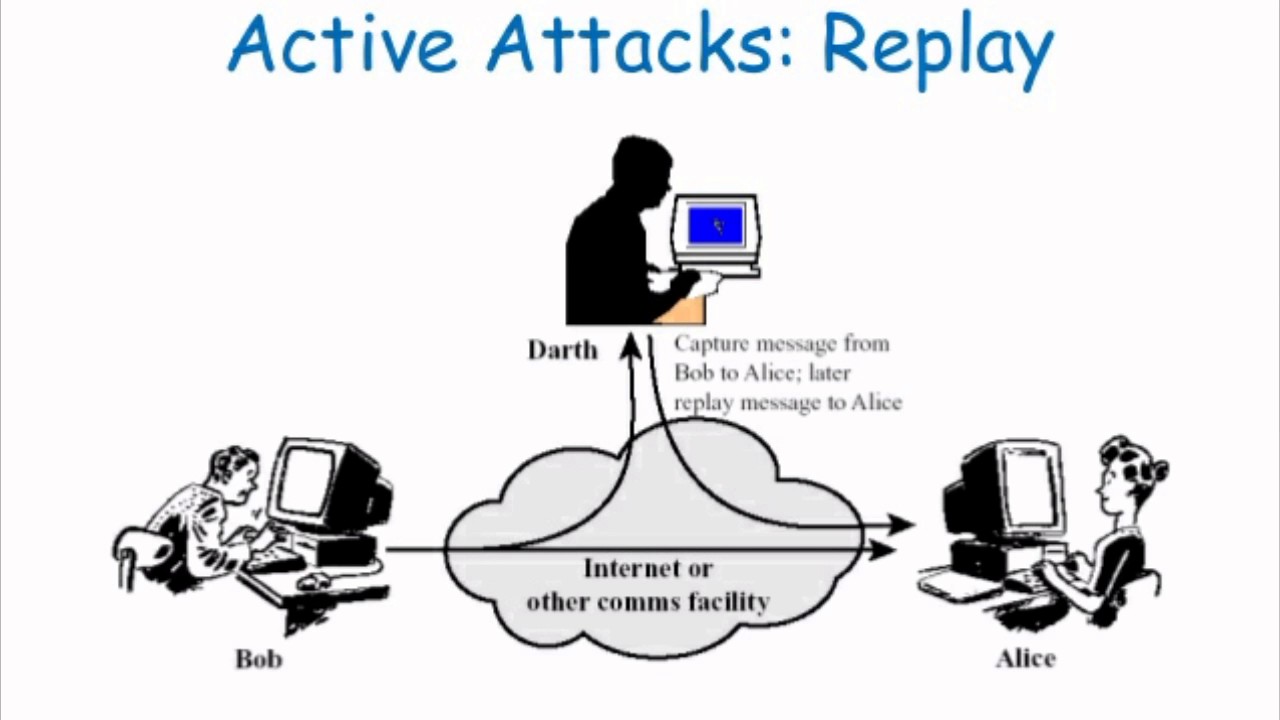
What I am to perform is called a replay attack. To explain it simply, a replay attack is simply a third party repeating a password that it overheard between two entities talking. If you overhear the secret phrase and it doesn’t change, you should be able to repeat this phrase to the door guard and gain entry as well.
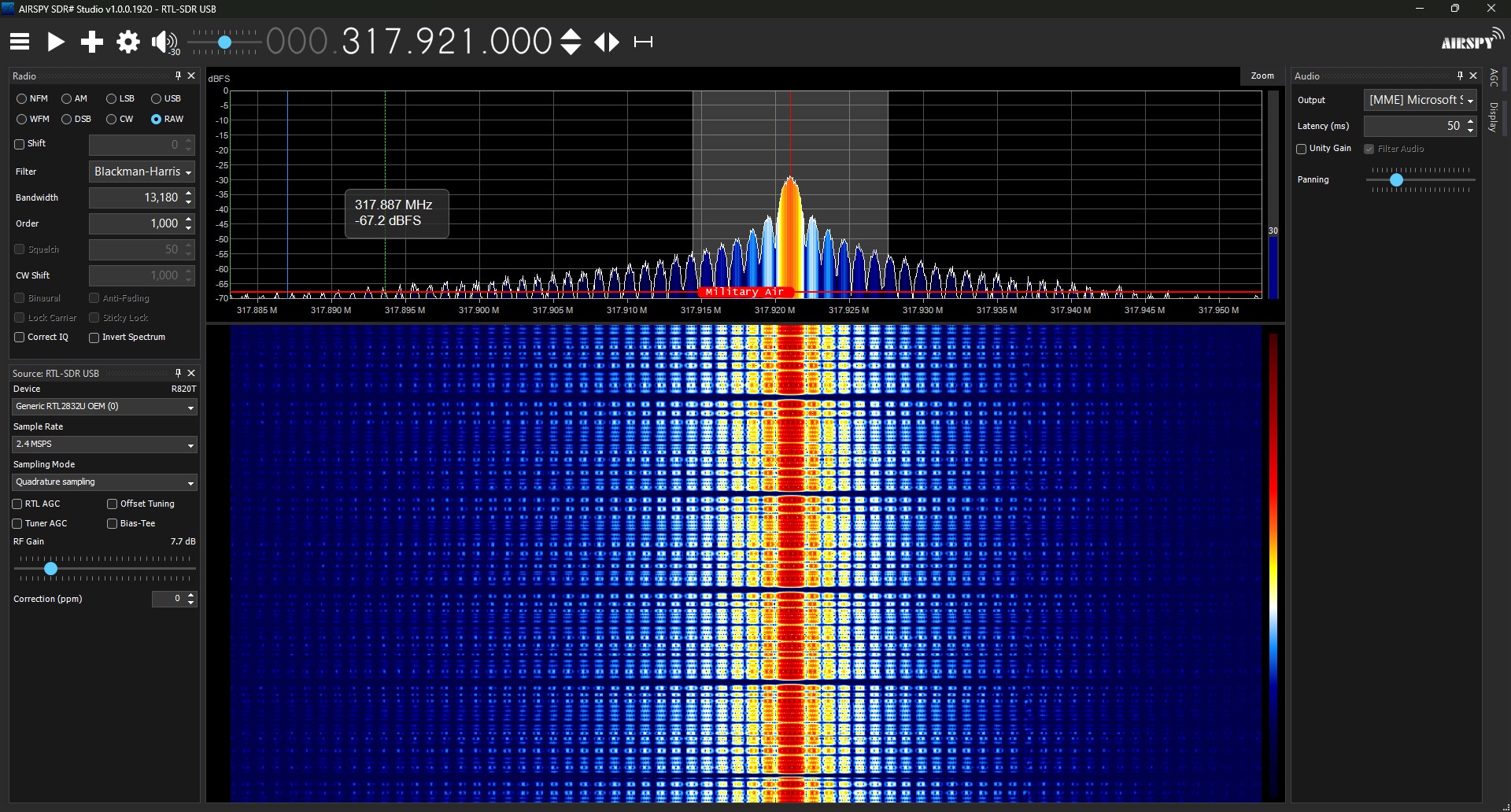
By listening in to what the garage door button was saying using our SDR, we can see from the signal that it keeps repeating the garage code on each keypress. This is a sign that the garage at the apartment will be vulnerable to a replay attack. To do this, we will need to overhear the password being communicated.
The Weakest Link
As a quick aside, I want to underline just how bad this is from a security point of view. Most people will think about their home’s security through their door locks, cameras, alarm and systems and think they are covered. But just how many people think about their garage as a vector of entry? Probably fewer people.
However, most personal home garages use a rolling code system, so they are not susceptible to the replay attack. This still does not make them impenetrable. If you leave the door to your house from your garage unlocked, I hope this demonstration will cause you to reconsider.
Inspecting the Signal
Back to the project. From AirSpy, we can see that the code being sent by these garage openers is the same on each press. At this point, we can see that the password repeats, but we cannot yet be sure what it is. In order to decipher the password, we must capture and analyze the signal sent by the opener.
In AirSpy, I set the receiver format to RAW to pick up the direct data coming from the opener. After centering on the opener’s band, I pressed record in AirSpy and then pressed the opener’s button a few times. AirSpy converts this recording into a WAV file, which can be opened in music editing software. I chose the prominent tool Audacity to inspect the file.
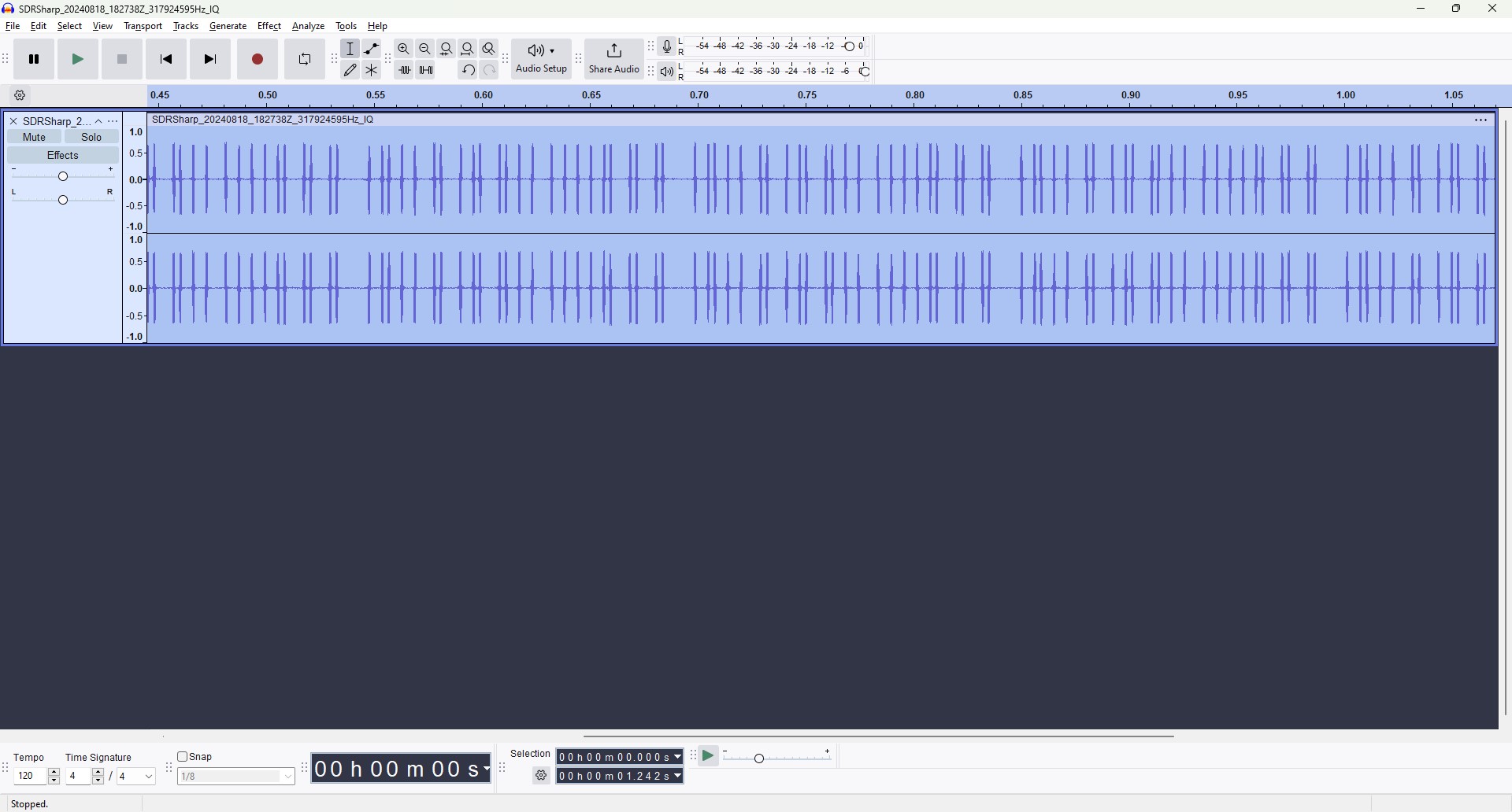
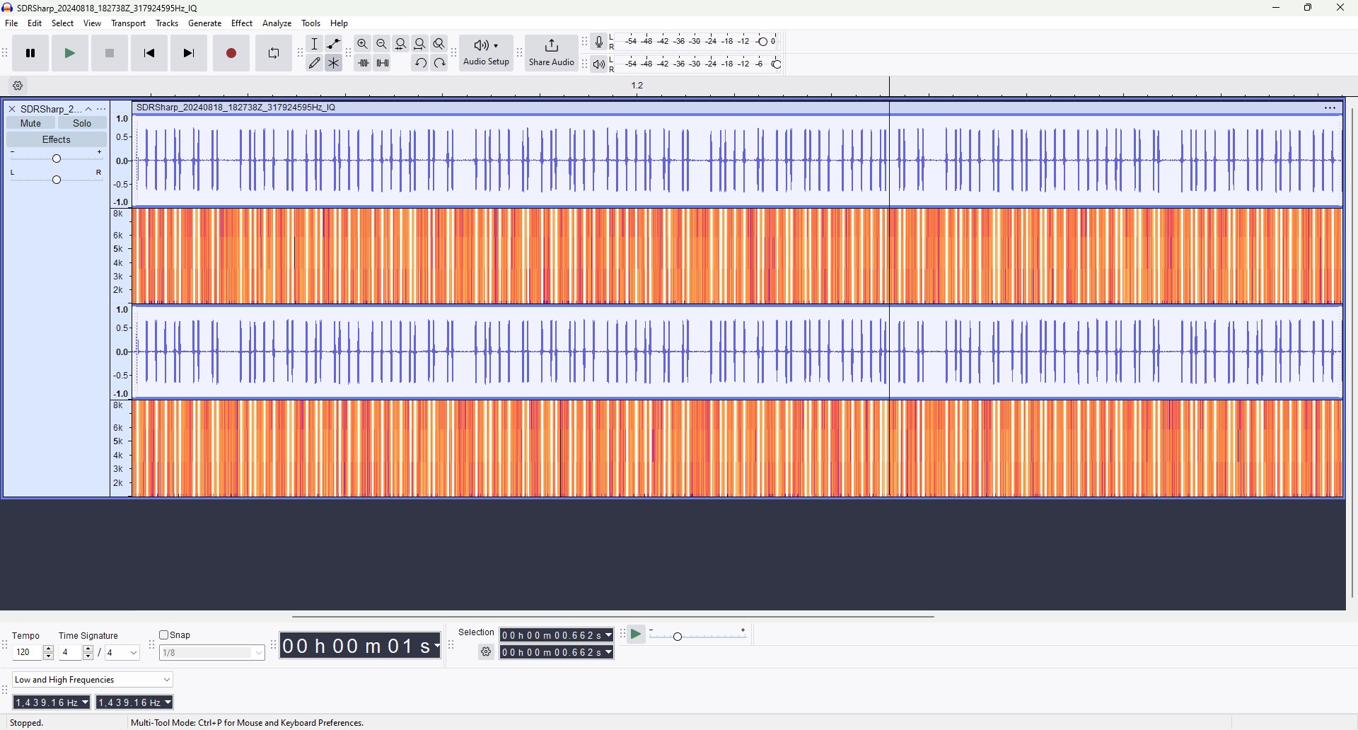
Why open it in an audio editing software? Surely not to listen to it. All information sent over radio waves are some type of wave signal. Sound is also a wave signal. If we can interpret sound waves using Audacity, we should be able to edit any kind of wave, especially since it was so nicely packaged as a sound file.
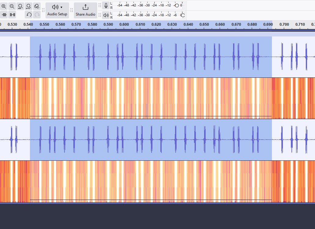
Opening the file in Audacity, we can see a patten emerge. This is a much more clear version of the chunky repeating pattern we saw in AirSpy. In the interface I enabled the spectrum analyzer, set the a wideband window size, and linearly scaled the response. By doing so, I divided the frequency spectrum into eight small bands. This, along with setting the frequency window to between 1-8 kHz completely eliminated higher frequencies in the signal, showing us the pattern more clearly.
Decoding the Secret Message
With the spectrogram filters set, we can easily each active pulse is the signal, and can more easily estimate their durations. Counting the blue spikes, there were 24 pulses transmitted. Isolating a single iteration of the code, we can see the full duration takes approximately 0.14 seconds to complete.
Recall from the FCC filing that the transmitter uses the Weigand 26 bit protocol. If we look up a chart of the Weigand protocol, we see that the first and last of the 26 bits sent are both parity bits, containing no data about the code. Since the code is bits (binary digits), we must determine the orders of the 24 1’s and 0’s in the code. As we repeatedly observed 24 pulses in our code, we can assume that this implementation does not include the leading and trailing parity bits.
Looking further into the FCC documentation, the included test report mentions that the devices use a “modified Manchester encoded modulation”. In our case, the modulation of the signal defines what is considered a one or a zero. The protocol defines what those ones and zeroes mean.
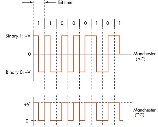
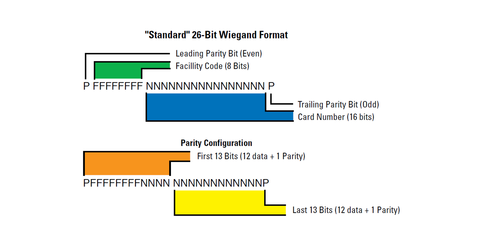
Using GIMP, I was able to overlay a square wave form to “clock” the pulses received. Since we know this is Manchester encoded, we will call each pulse on the low side of a clock period a 1, and those on the high size a 0.
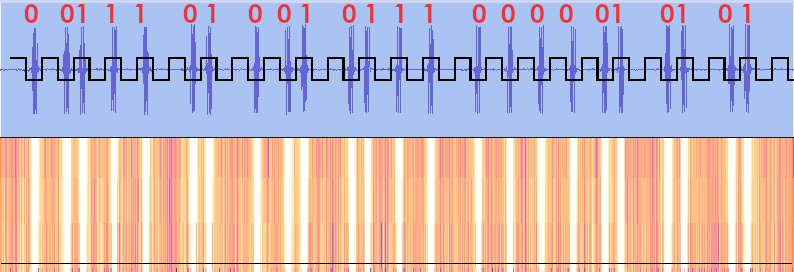
As a side note, whether a low clock represents a 1 or 0 is arbitrary. If we decided that the first bit was a 0, then all the following bits would be flipped. This is acceptable, as the Manchester encoding is self-clocking. As long as we get the relative duration and spacing of our pulses right the final code will be correct.
For Aspiring Hackers
We happen to know the modulation technique because we found it in the FCC filing. But what if we didn’t? We can decode this signal if we can figure out its modulation. Based on our received signal, we can count out several modulation techniques right away. The pulses are all the same width, same frequency, and same duration. We also note that they all seem disjoint; no two pulses are touching.
- Amplitude Modulation (AM): Probably not. All of our pulses are the same height.
- Frequency Modulation (FM): Also no. All of these pulses were sent on the same 318 MHz band.
- Pulse Width Modulation (PWM): All pulses are the same width.

In the worst-case, you would want to traverse the tree of options from the Wikipedia article on modulation until you found one that made sense for your signal.
Signal Interception
The software defined radio that I had purchased worked at a surprisingly long distance. In theory, it would have been possible for someone to sit in their car near the entrance of the garage and wait for someone to press their button to enter. If that someone had been tuned to the correct frequency and recording on their SDR running on their laptop, perhaps sitting inconspicuously in the passenger seat of their car, they might be able to “sniff” a correct signal to be later decoded. Again, in theory.
I happened to have a roommate who was more than happy to help me with my little science project, and allowed my to record their code.
Signal Replay Hardware
At this point in the endeavor, I have unearthed the secrets of the garage door opener, learned how to collect its transmissions, and decoded the transmission into its binary format. Exciting, but what do we do with the code now that we have it? This is where the replay comes in.
My next goal is to transmit that signal, in the correct timing, at the right frequency. Fortunately, I have a device that transmits at 318MHz: the new garage door button from Amazon. If I can get it to send out the right signal, it should open the door. To do that, we will need to modify the hardware.
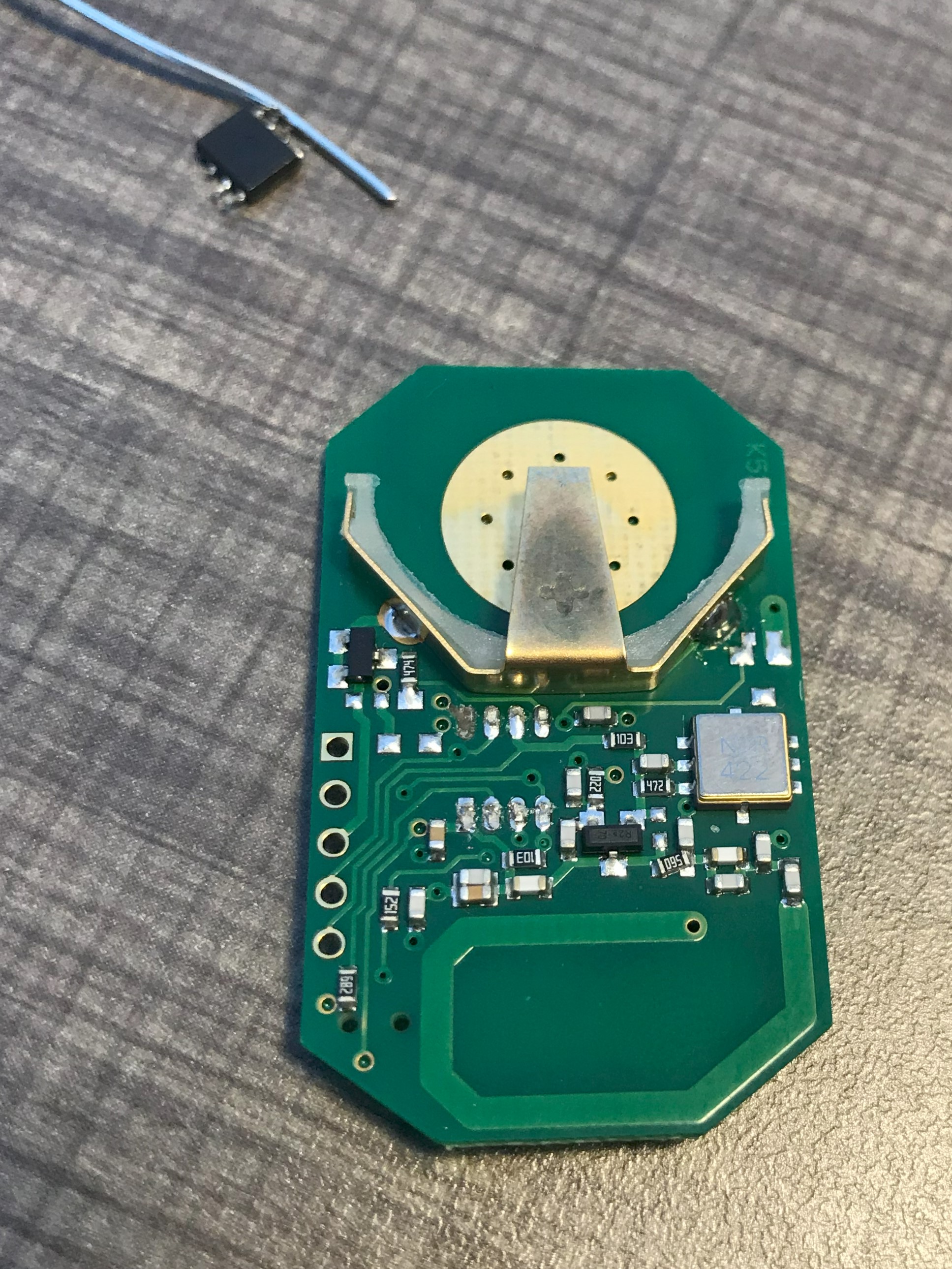
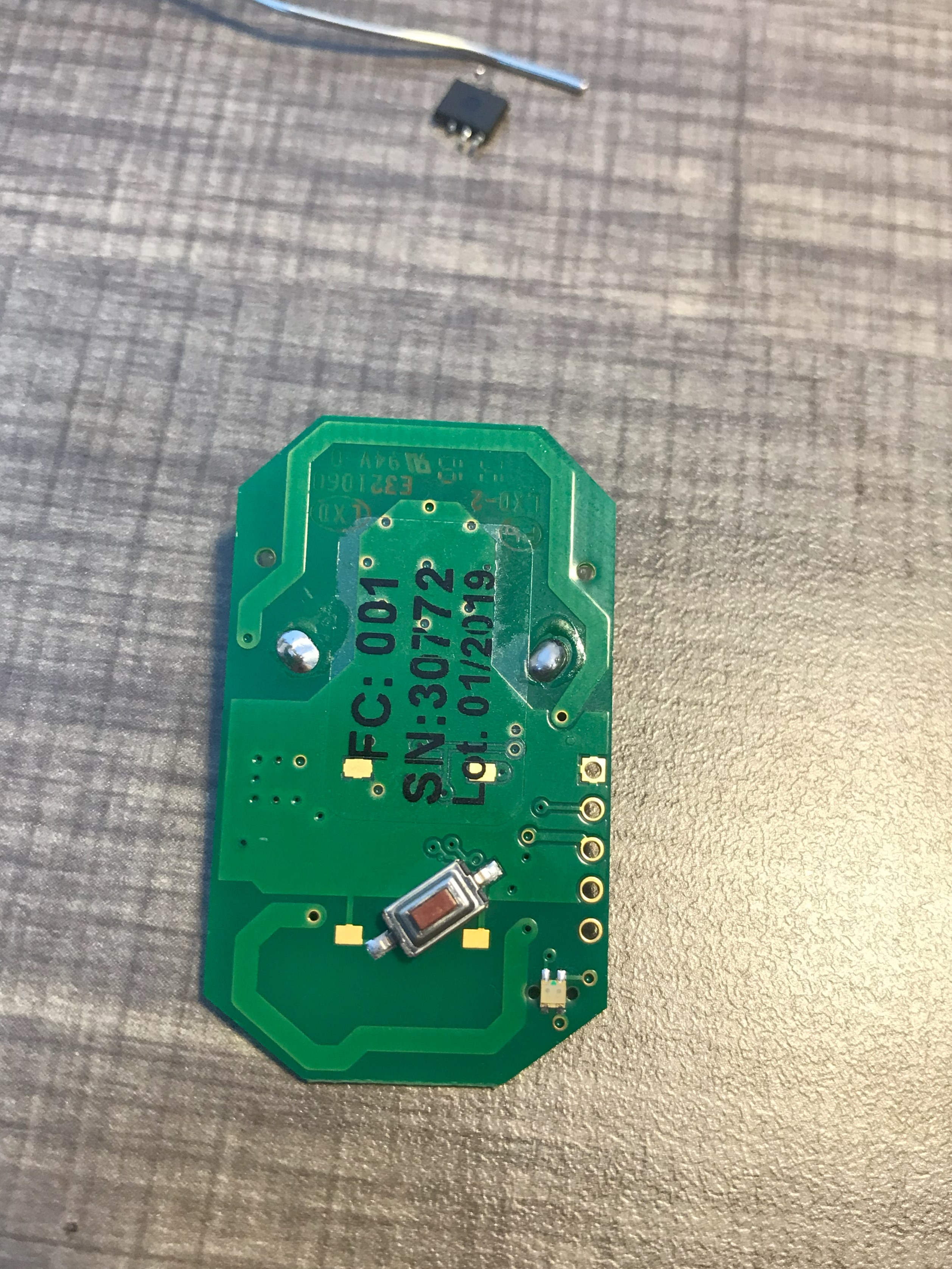
Opening the button’s enclosure reveals the PCB and its internal components. Looking inside, we see a button, an LED, an oscillator, a handful of resistors, and a tiny microcontroller. That microcontroller is responsible for sending out the signal, sending it to the oscillator and then the transmitting antenna. Since the controller only has 8 pins, a little studying yielded the pinouts that I needed.
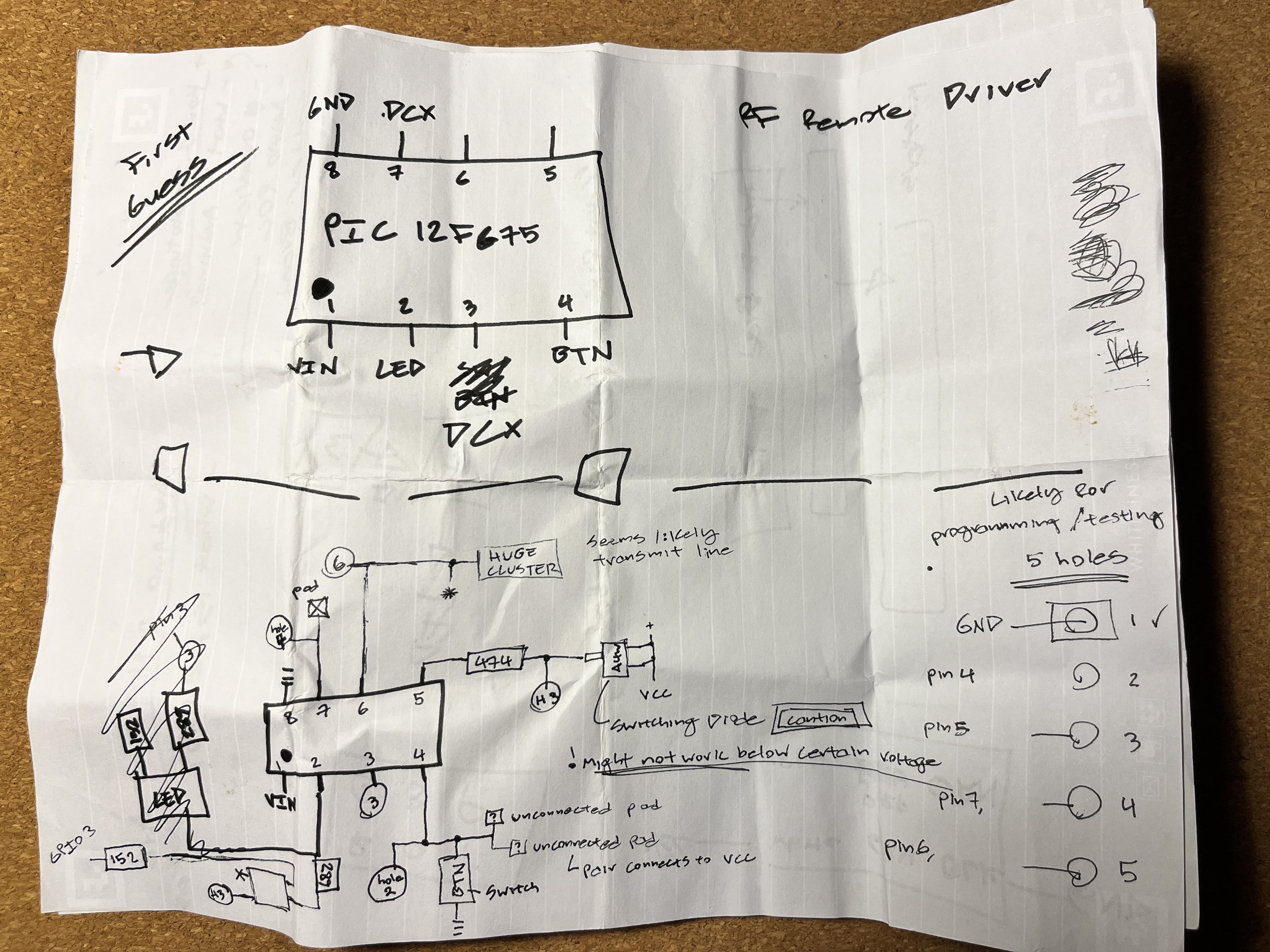
Replacement Microcontroller
To get the button to transmit the code, I needed to replace the microcontroller with a new one, programmed to send a correct code. I elected to replace with with an Atmel AT-Tiny45, a very inexpensive 8 pin MCU. I could use the timing from Audacity to determine the clock period and pulse width, which I then translated to Arduino code.
// MICROSECOND DELAYS CHANGED TO COMPENSATE FOR INTERNAL CLOCK ERRORS
#define SIG 7 // Unused
#define CLK 4 // Was 8 on Arduino Nano setup

const float CLOCK_ADJ = 1.0876; // Account for imperfections in ATTiny45 internal clock
const int PERIOD_MICROS = 5860; // Microseconds between each rising clock
const int PULSE_MICROS = 977/CLOCK_ADJ; // How long a pulse takes
const int WAITING_MICROS = (PERIOD_MICROS-(2*PULSE_MICROS))/CLOCK_ADJ;
const int DELAY_MILLIS = 488/CLOCK_ADJ; // Time between code transmissions

uint8_t code[] = {
  1, 0, 1, 0, 1, 1, 1, 1, 0, 0, 1, 1, 1, 1, 0, 1, 0, 1, 0, 1, 1, 0, 1, 0
};

void setup() {
  pinMode(CLK, OUTPUT);
  digitalWrite(CLK, LOW);
}

void pulse(uint8_t value) {
    if (value != 0) {
        delayMicroseconds(WAITING_MICROS);
        digitalWrite(CLK, HIGH);
        delayMicroseconds(PULSE_MICROS);
        digitalWrite(CLK, LOW);
        delayMicroseconds(PULSE_MICROS);
    } else {
        delayMicroseconds(PULSE_MICROS);
        digitalWrite(CLK, HIGH);
        delayMicroseconds(PULSE_MICROS);
        digitalWrite(CLK, LOW);
        delayMicroseconds(WAITING_MICROS);
    }
}

void loop() {
  for (int i = 0; i < 24; ++i) { pulse(code[i]); }
  delay(DELAY_MILLIS);
}
As seen by the constant CLOCK_ADJ, the internal clock in the chip was not very accurate. After some playing around I was able to get the timing to be correct by scaling the time values linearly.
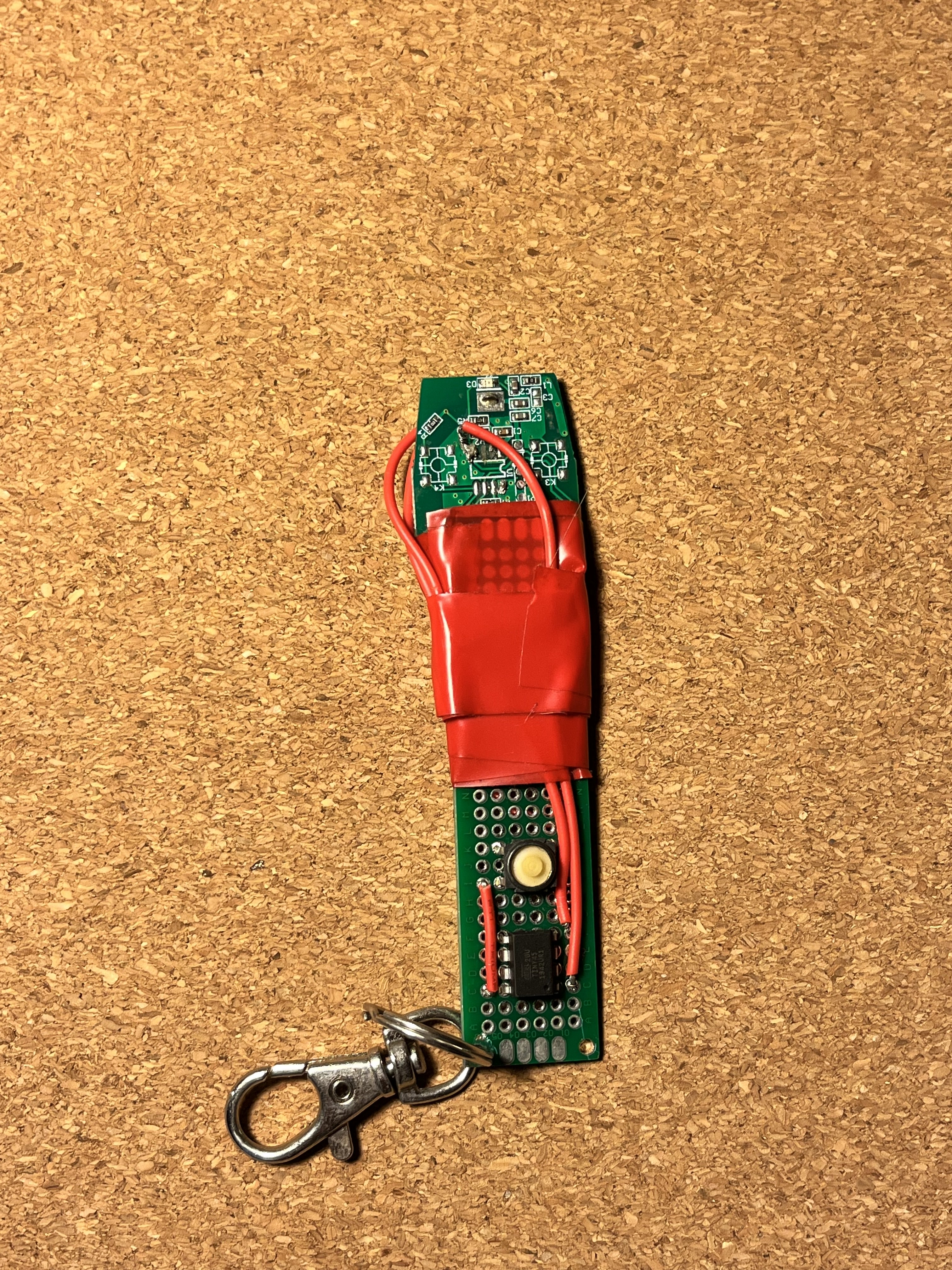
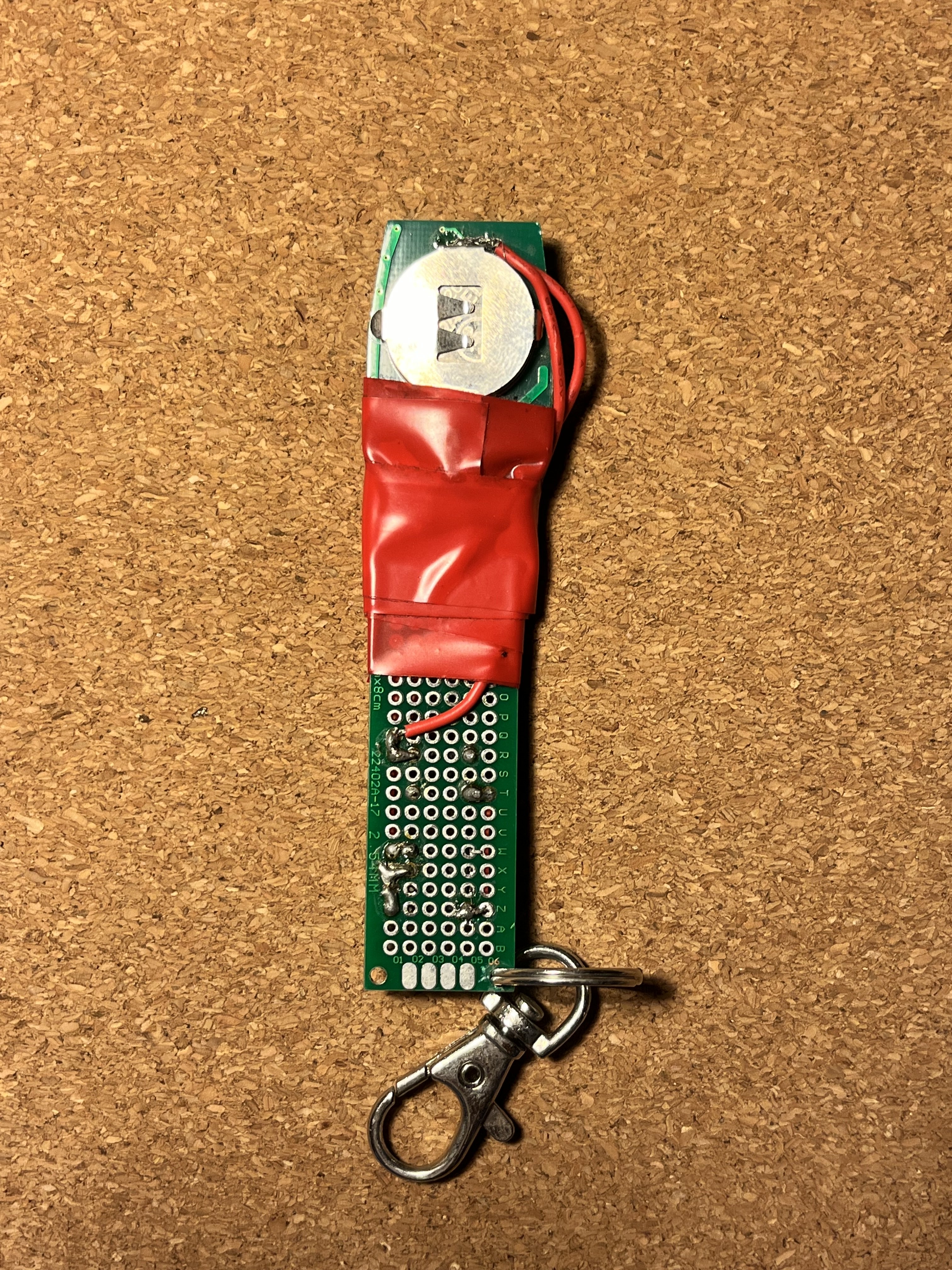
After programming the ATTiny45, I now had a microcontroller sending the correct code with the correct timing, and a device to transmit this code at the correct frequency. To bring the two together, I soldered the chip into some perfboard and connected its pins to the garage door opener PCB with some wires and solder.
Reflections
This project ends in the most anticlimactic fashion. Although my device worked according to plan, I never needed to use it. Turned out, my apartment was happy to replace my fob for less than the cost of the Amazon SDR. Go figure.
All was not lost. I learned so much about RF, the ISM bands, FCC filings, and different means of signal modulation by creating my replacement fob. Reverse-engineering is an excellent way to learn about an unfamiliar system if you have the patience for it. The clunky perfboard setup also necessitated my first need to create a custom PCB, which I would teach myself in a project later that summer.
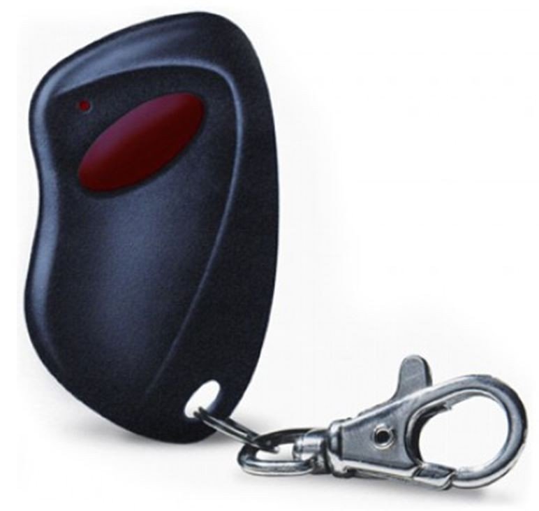
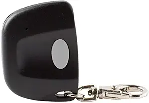
This project also opened my eyes to just how vulnerable so many homes and businesses are to the most basic hacking attacks. To this very day I can look at most garage fobs and know if it is easily susceptible to a similar attack as demonstrated above. When you find your keys again, double-check to see if your garage button looks like any of the images below. If it does, I would recommend you lock the door going into your garage when you leave your home. They may be hackable.

