Follow-me Lights
Writeup coming soon!
COVID Blues
Trial and Error
The First PCB
Baby’s First Schematic
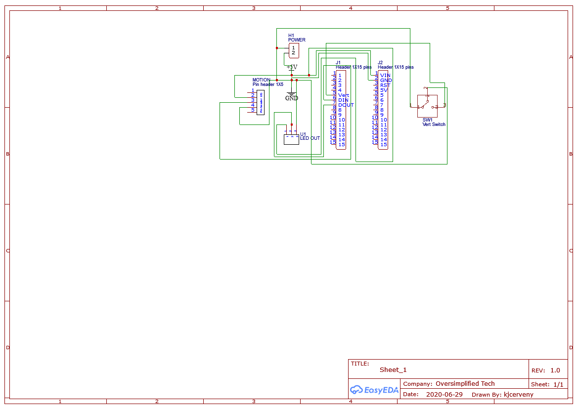
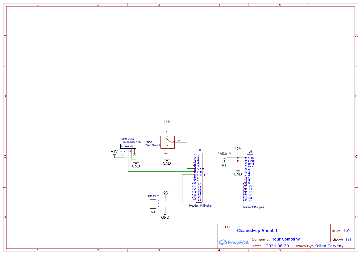
Sorry in advance for this first schematic. In my defense, this really was the first one I ever made. At the time, I did not know you could label your nets, so I made sure that every ground and power wire were connected, leaving a tangled mess. Pretty impressive, considering that the whole board only had five total components, and over two thirds of those wires are just for power.
For your amusement, I included my first draft. To the right is one easier to understand. This board is mostly used to transfer power between our components, and some signals too. The POWER IN powers the full board. The two 15 pin headers attach to an Arduino nano clone, which accepts the motion signal from the RCWL-0516 motion sensor, and drives the attached LEDs. If the VERT switch is off, the LEDs will not illuminate.
v1 PCB Design
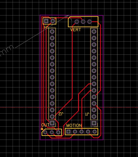
Much like the schematic tomfoolery above, this PCB demonstrates a few rookie mistakes. The prospect of making a two sided PCB with vias was intimidating to me at the time, so I routed every wire across the top. Honestly the auto-router may have done a better job. My biggest concern with this board looking back is the fact that the power traces are just so skinny. For the amount of amperage the LEDs demanded, I am shocked this even worked.
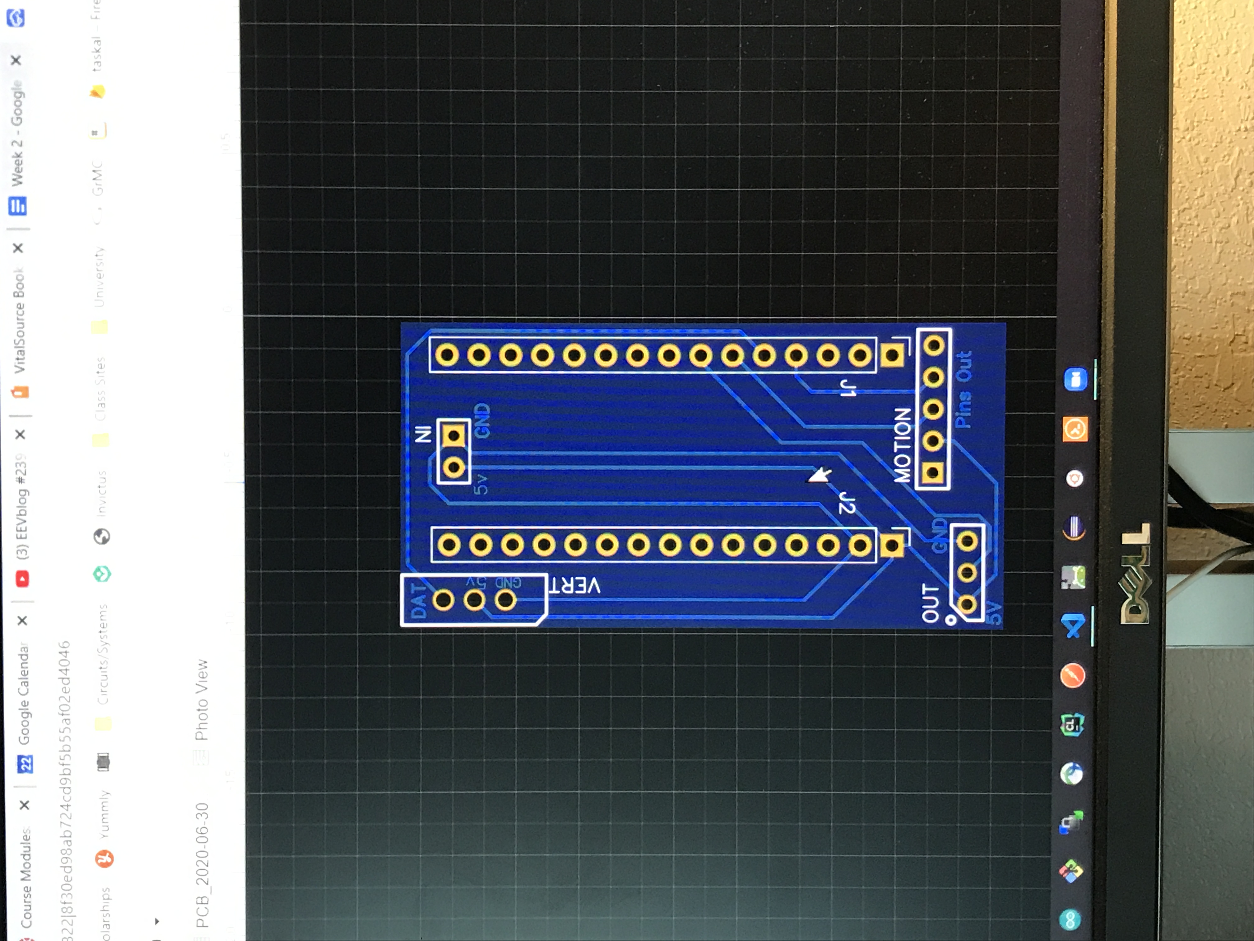
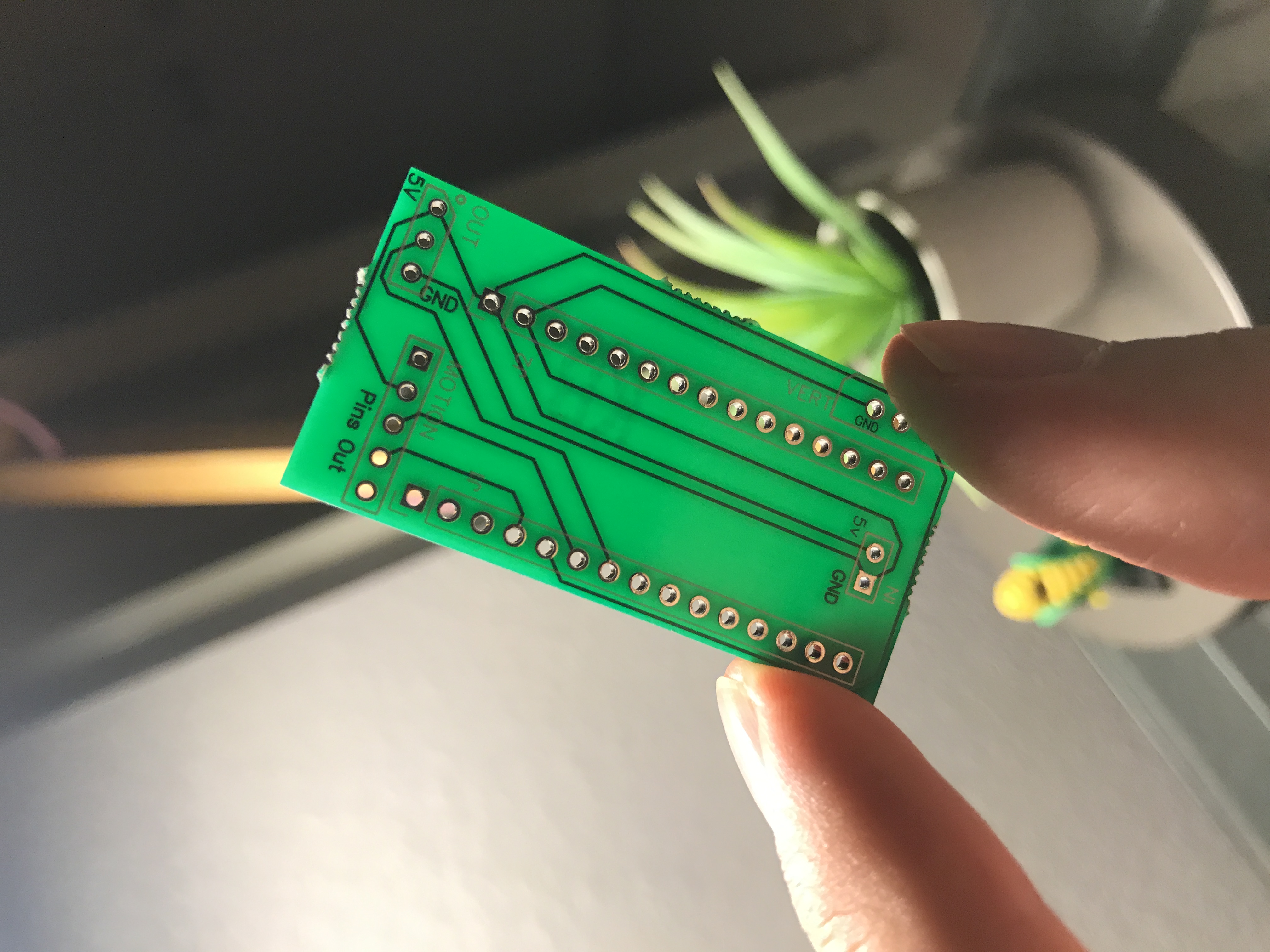
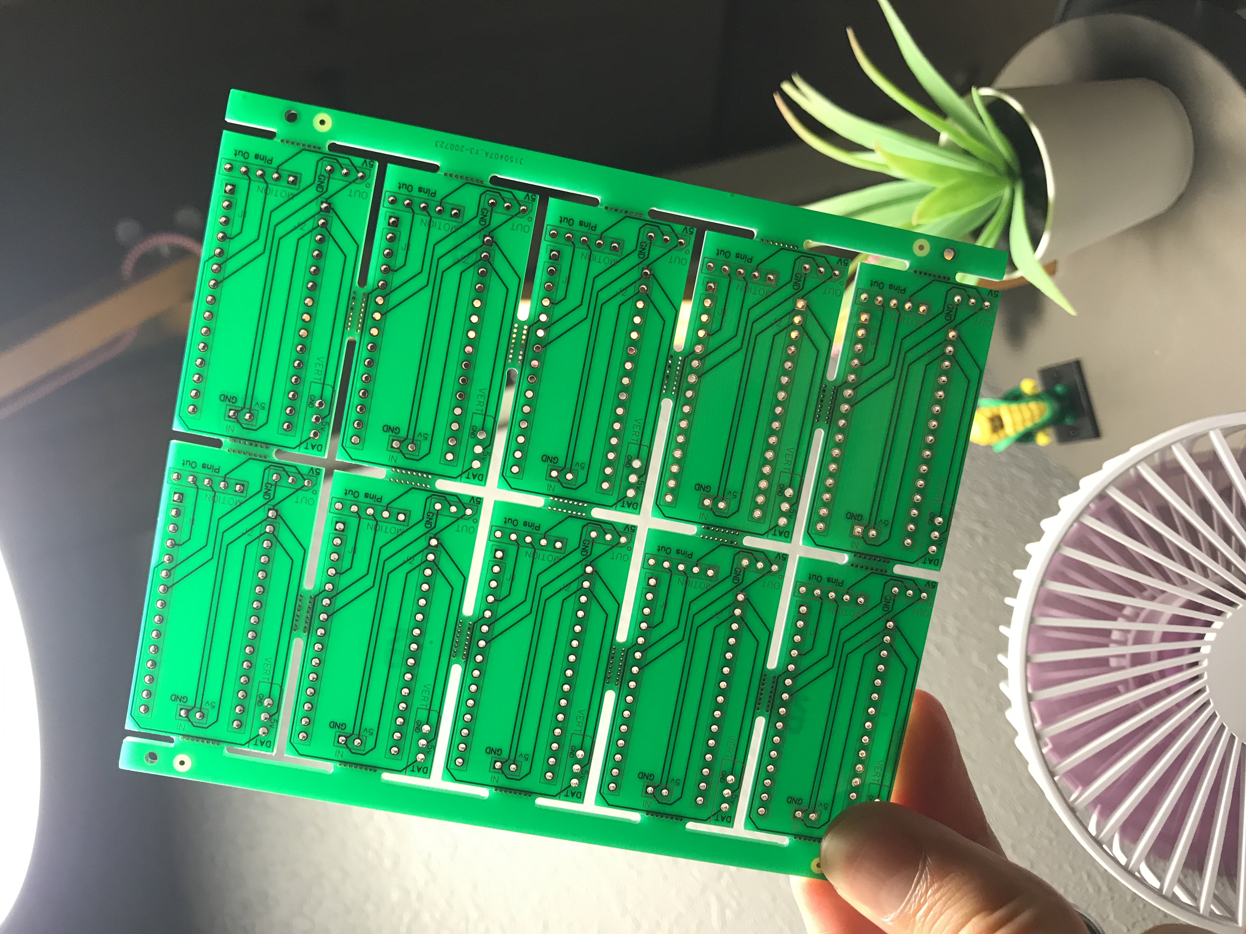
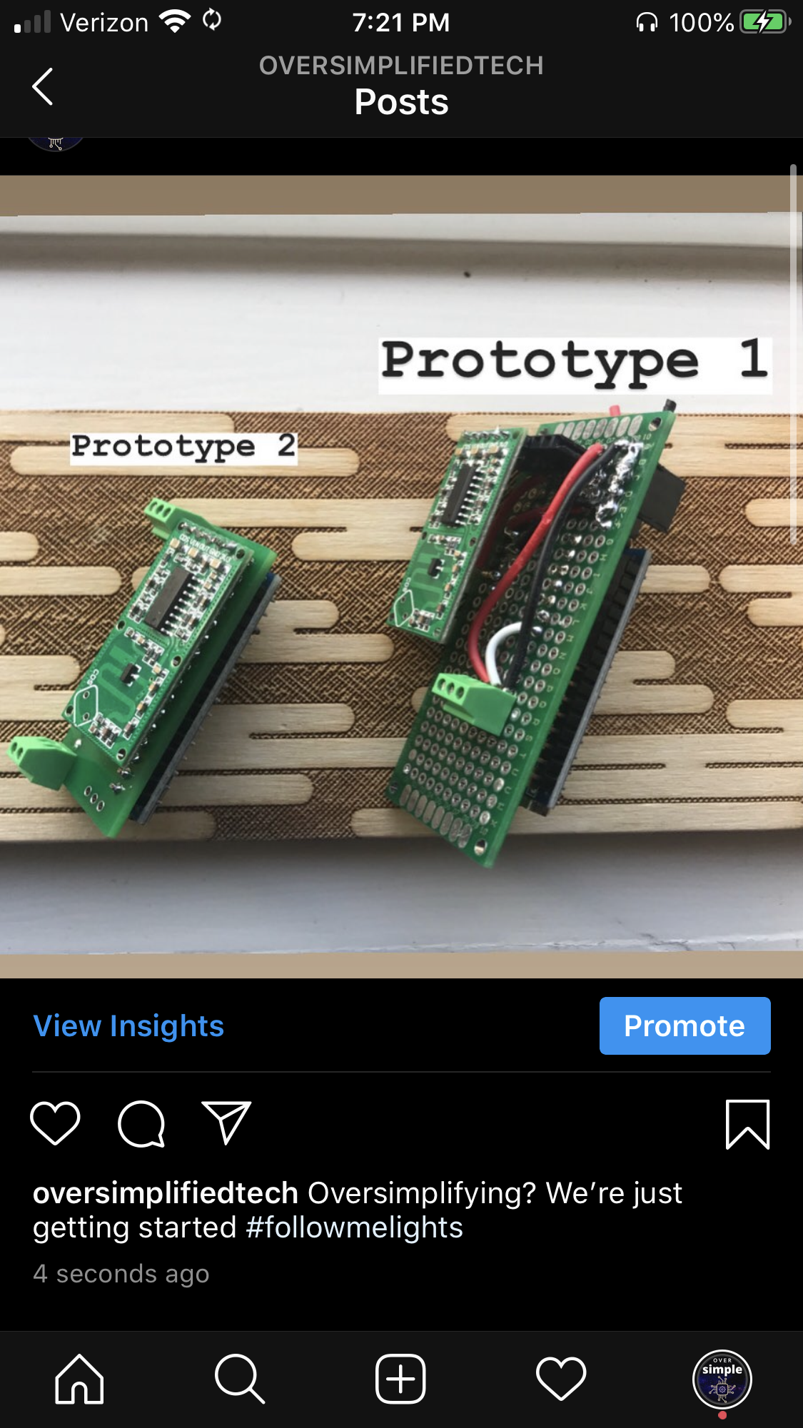
Fortunately, these boards actually worked exactly as intended. Not only did these save an immense amount of time on assembly, they were also smaller, more rugged, and less prone to shorts. Those reasons were all why PCBs were invented in the first place, but I really earned an appreciation for them after struggling against the perfboards for so long. Below you can see the huge difference the new PCB made on the size of the LED driver.
Scaling Hardware
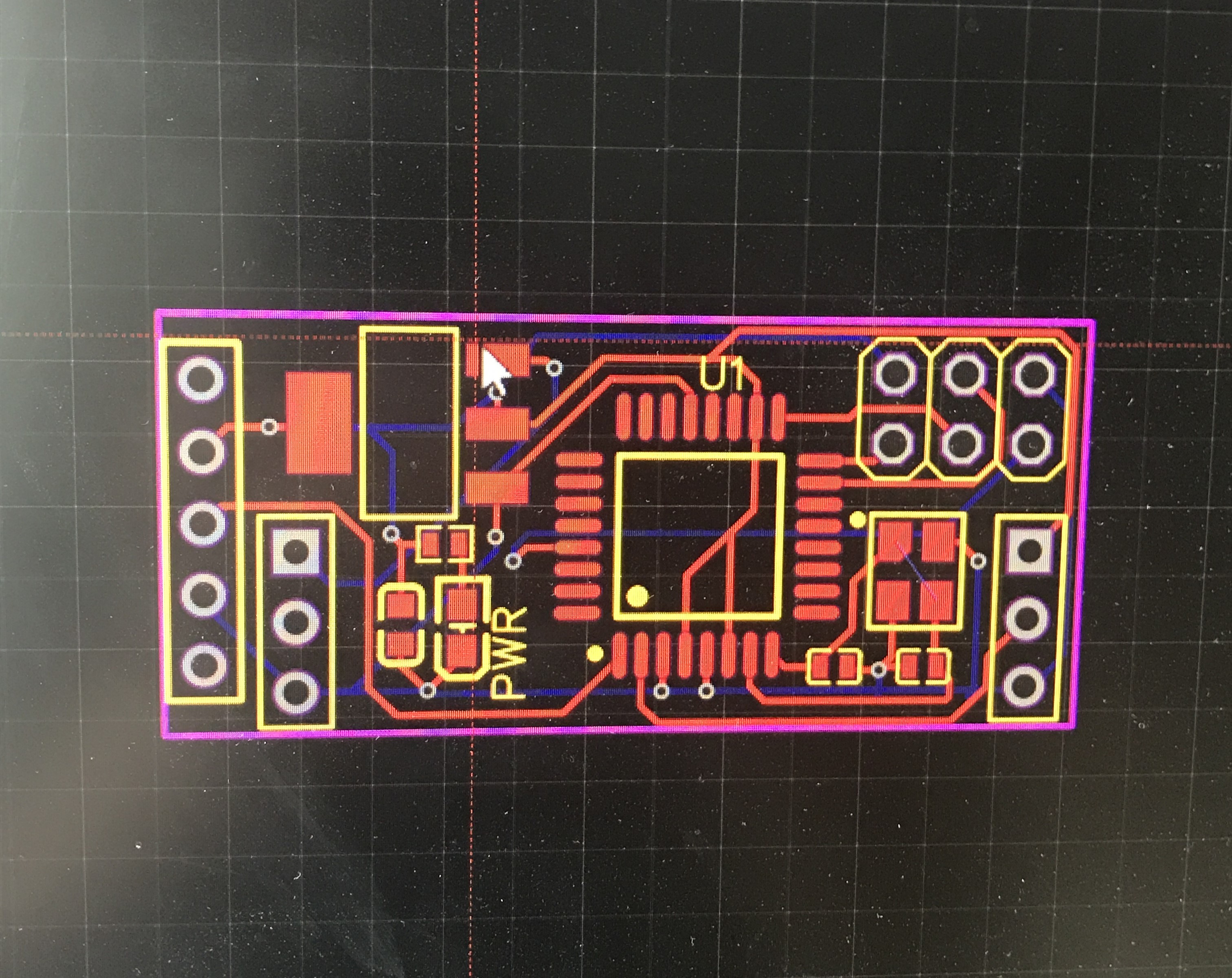
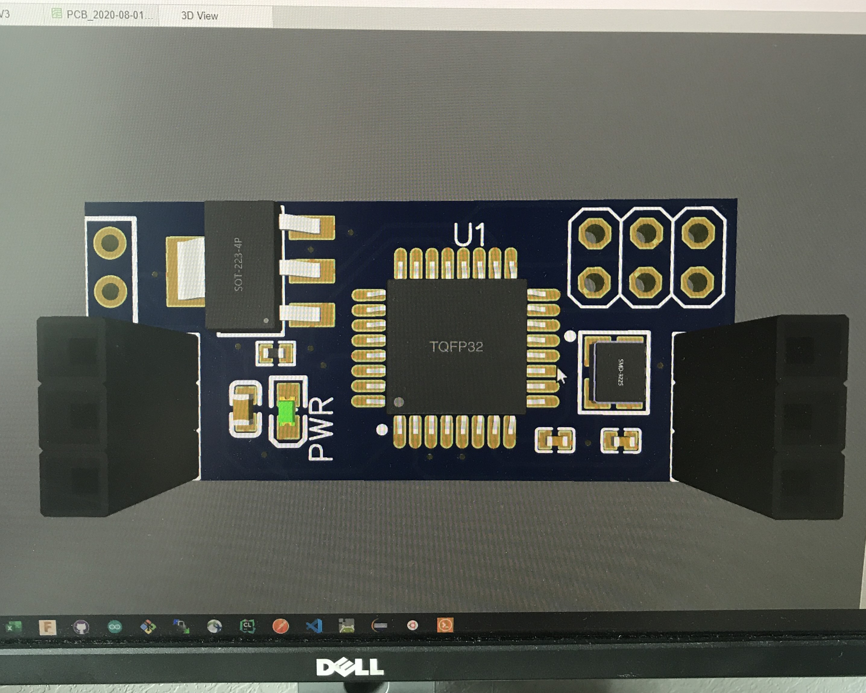
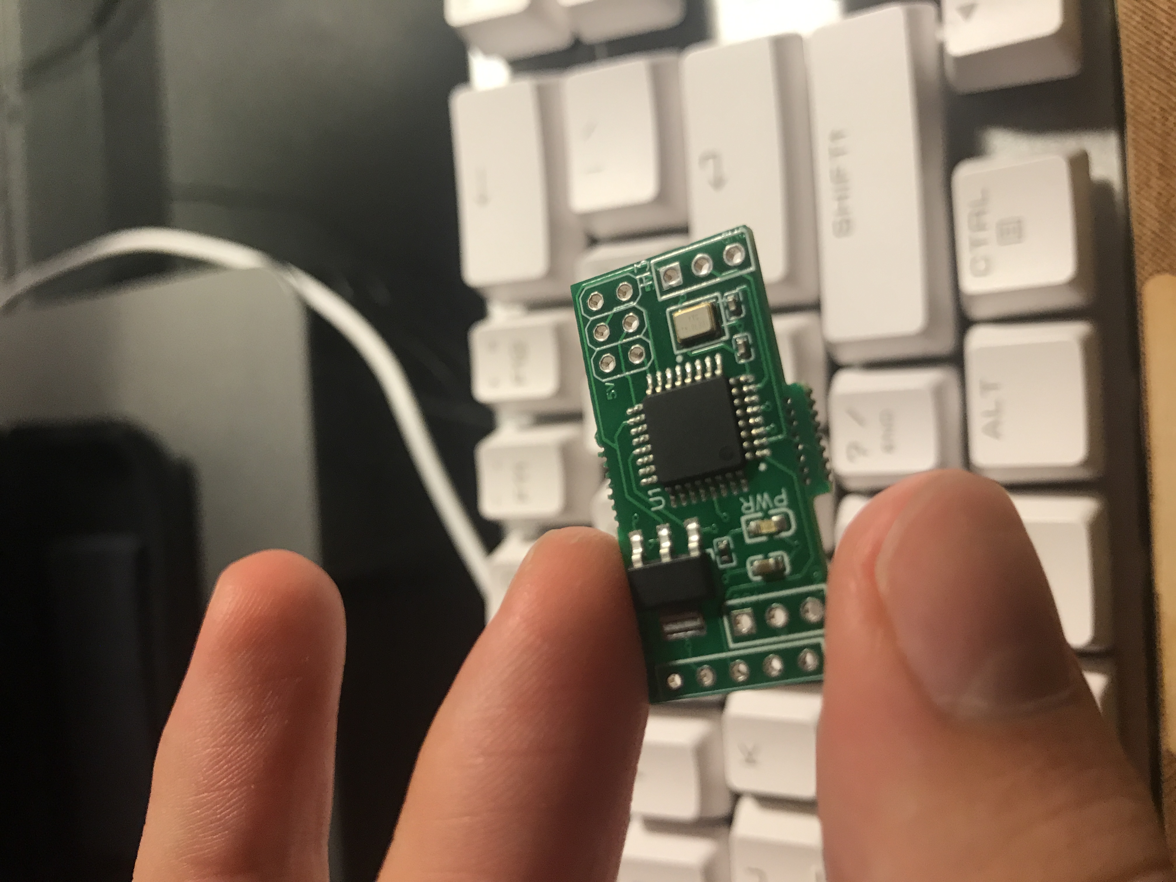
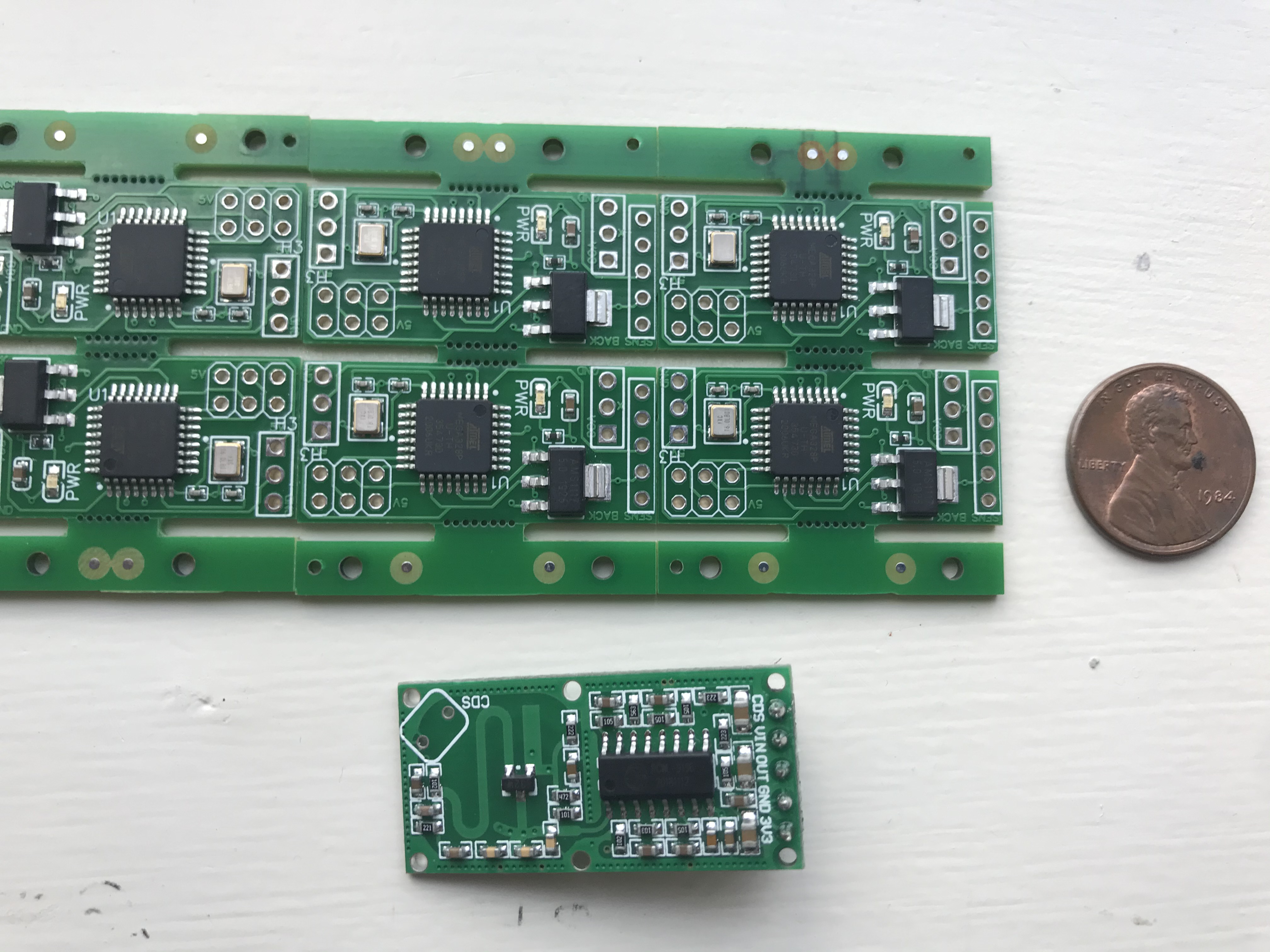
So we had a huge improvement in the size and assembly of the LED driver, but it was not yet ready to be a real project. Mainly, this design was using a full Arduino Nano clone development board, soldered directly to the PCB to save space. Although we could get them cheaper in bulk, the product was still going to be too large and too expensive to take to market. We needed to skinny this down further.
V2 Design
