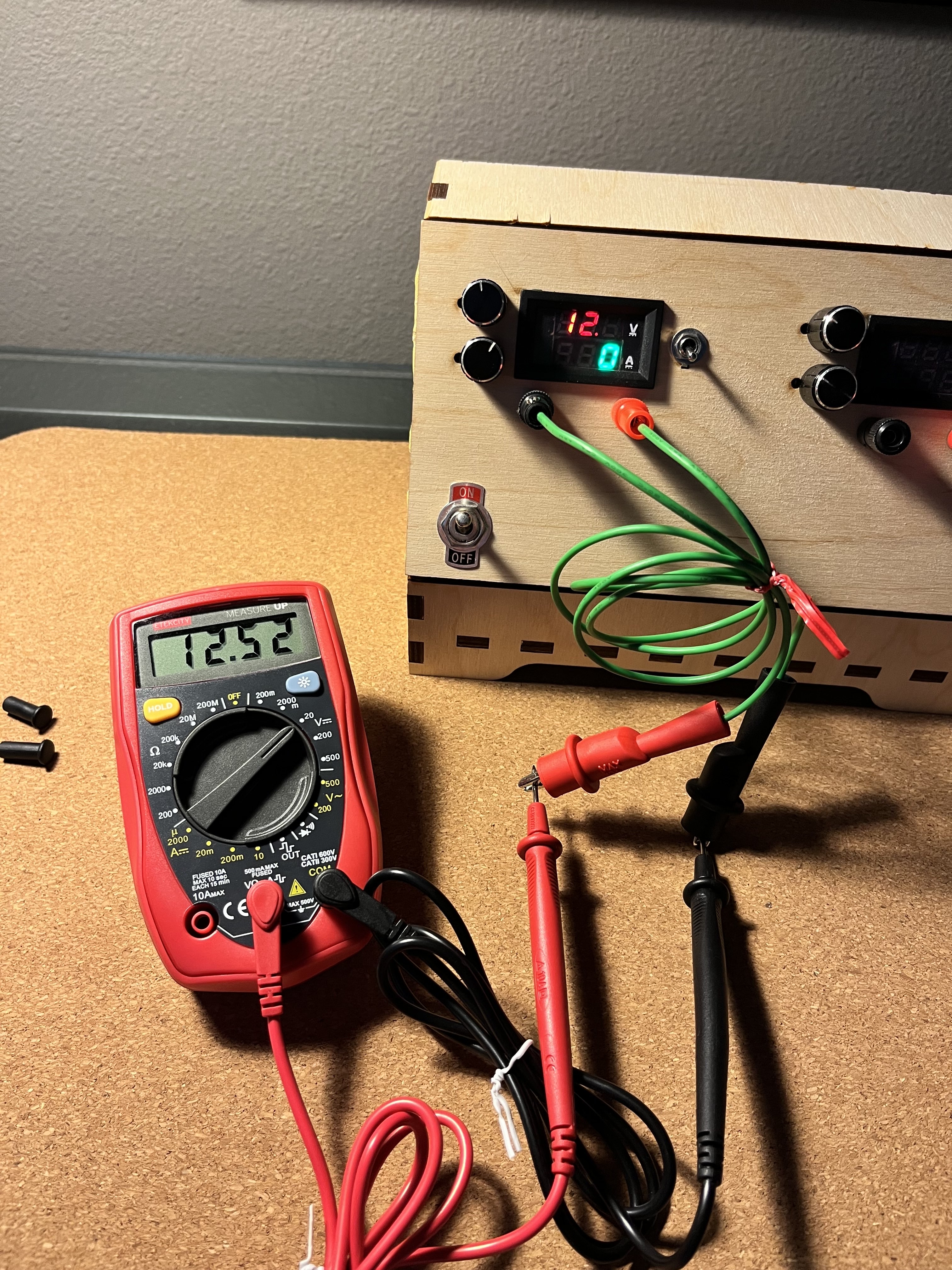
Bench Power Supply
Your handy companion for electronics projects
Background
If you ever dive into the wonderful world of electronics tinkering, you will find a few common requirements across your projects. Many times you will need simple hardware, such as a breadboard, resistors, wires, or a multimeter. Anyone can find these on Amazon for around $30, and most kits are about equally good. Some beginner tutorials will even link directly to kits that are suitable to follow along.
As your projects grow more advance, some of the requirements will change. Often this will mean finding less common parts for your project. Sometimes, this means finding less common voltages. But what do I mean by a less common voltage?
Normal Tinkering
For many, many Arduino projects, you will use one of the two voltages produced from the pins of the board. These will be 5 volts DC and 3.3 volts DC, almost invariably. The history of this is quite interesting, but I am going to skip some parts of it today. Instead, I will just explain from where these voltages are produced.
The 5 volts DC is actually not being generated by the microcontroller, but rather the USB powering the microcontroller. All USBs will give out 5 volts. That is part of the universal in universal serial bus (AKA the USB). This is a good thing! Imagine what a mess things would be if you plugged your phone in to charge in a USB outlet and it had 500 volts DC, frying your CPU. Very bad! To prevent this, electrical engineers agreed to use the 5 volt standard.
What about the 3.3 volts? Many electronics used to be powered by 5 volts. It was not until later that scientists discovered ways to get the same performance from their electronics using 3.3 volts instead, saving power and extending battery life. Because of this, Arduino-type boards will have an onboard voltage regulator, which brings the 5 volt power coming in from the USB down to a smooth 3.3.
TLDR; Arduino projects will always give you access to 5 volts and 3.3 volts DC.
Abnormal Tinkering
Now here comes the problem. What if you are trying to work with some neat LED lights and they require 12 volts of DC power? Unlike most projects, you won’t be able to get it from your Arduino-like board, nor your computer’s USB. And you certainly can’t get it directly from your wall (~120 Volts alternating current for Americans). So what’s your move? Enter the power supply.
The variable DC power supply is a device invented to solve this very problem. Each supply channel will have two dials, one to set the voltage and the other to set the current limit. If you need 12.5 volts of DC power, simply turn on your supply, set it to 12.5, and use the positive and negative prongs as your power leads.
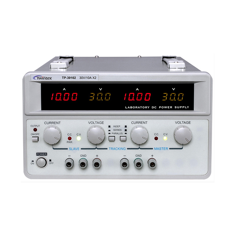

Of course, this is not how this problem gets solved in professional products, but it is a very useful tool for experimenting when you don’t want to build a real voltage regulator. They are an electronic miracle for prototyping and tinkering. The only problem is that a good one can be a little bit too expensive for a college student, like myself at the time.
Find a Way or Make One
In college, I did not have the resources to buy myself an expensive power supply so that I could have 12.5 volts for my lights. I did, however, have the resources to make one. After my exciting success building a machine in the labs of Texas Inventionworks, I felt confident in trying to build another device.
In my experience working at TIW, I was introduced to a phenomenal tool called boxes.py. It is an incredible piece of open source software that helps people plan laser cuts to for common objects without needing to painstakingly design every single finger joint. It is not an understatement to say that this tool is revolutionary for laser cutting projects. Without it, so many ideas would be inaccessible just due to the design cost of the joints.
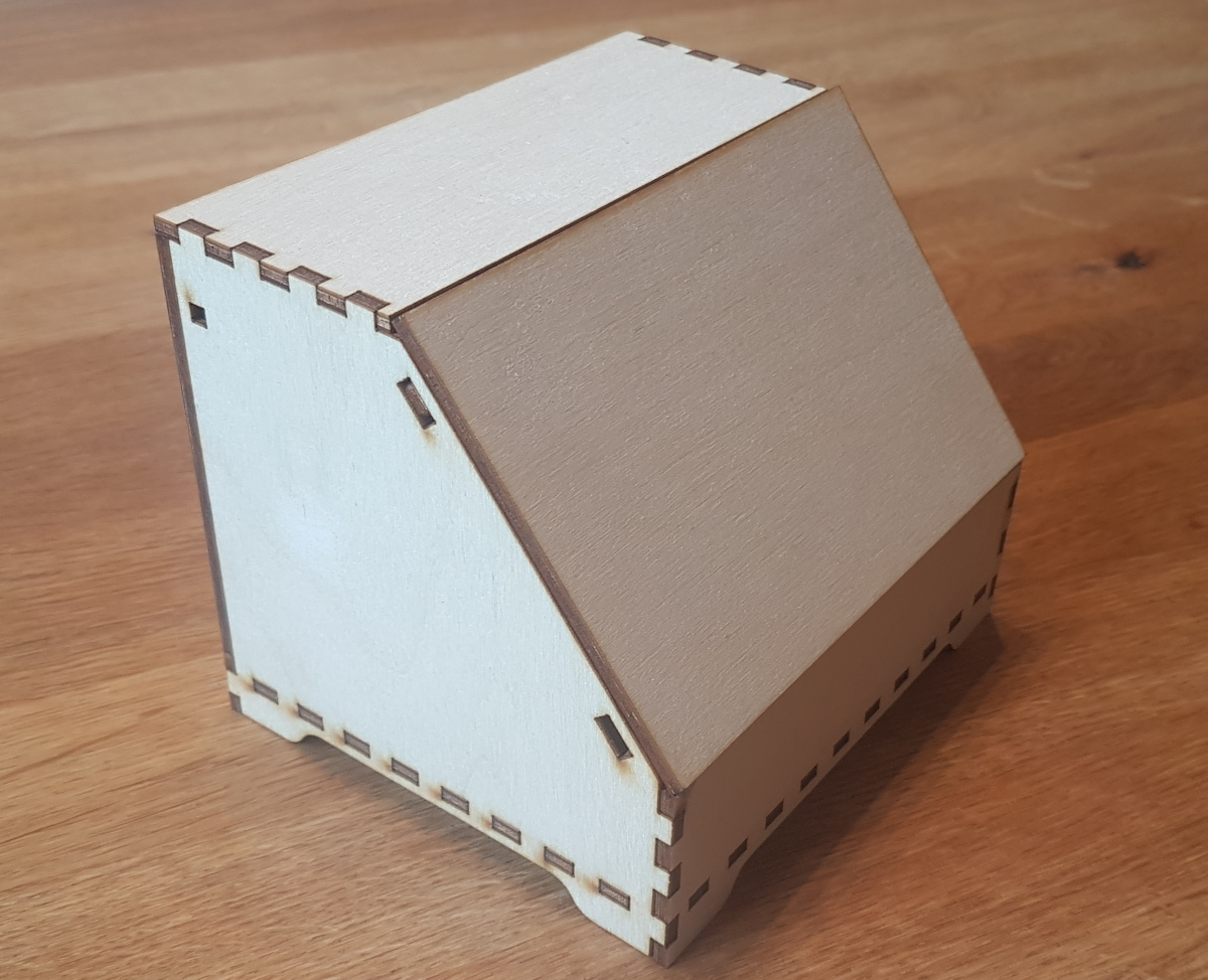

Can you imagine doing that by hand?
Despite its name, boxes.py is not just for boxes. In fact, they continue to add new and interesting generators to suit makers’ needs. I found one titled Console2, useful for creating tabletop console-like boxes. This was the base I chose to serve as the case for my power supply. All this required was to set the parameters correctly and later design the faceplate, which would house the interface for the power bench.
Excellent. Now we have a good looking box. Next we need the actual power supplying part.
Electronics Design
There are a number of ways to approach the variable power supply circuit. My primary goal was to minimize the cost by using parts that I already had or could get cheaply. My approach was to take a pre-built DC power supply and add some components to it such that we could control both the amperage and current, making it a variable power supply.
Roger, my mentor at Texas Inventionworks, allowed me to raid a box of old laptop chargers. I found one for a long-gone MacBook (Powerbook?) that satisfied the requirements. The charger block offered a solid 30V of DC power.
Here was the plan:
- DC Power supply converts wall power from 125VAC to 30V DC.
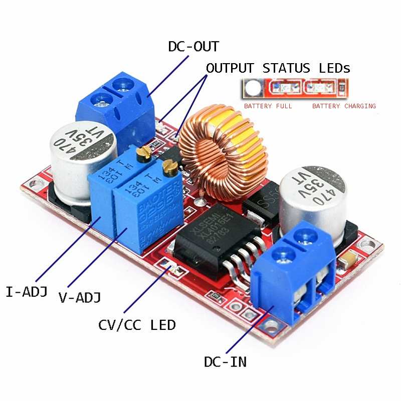
- DC-DC buck converter converts our 30V to whichever voltage we choose.
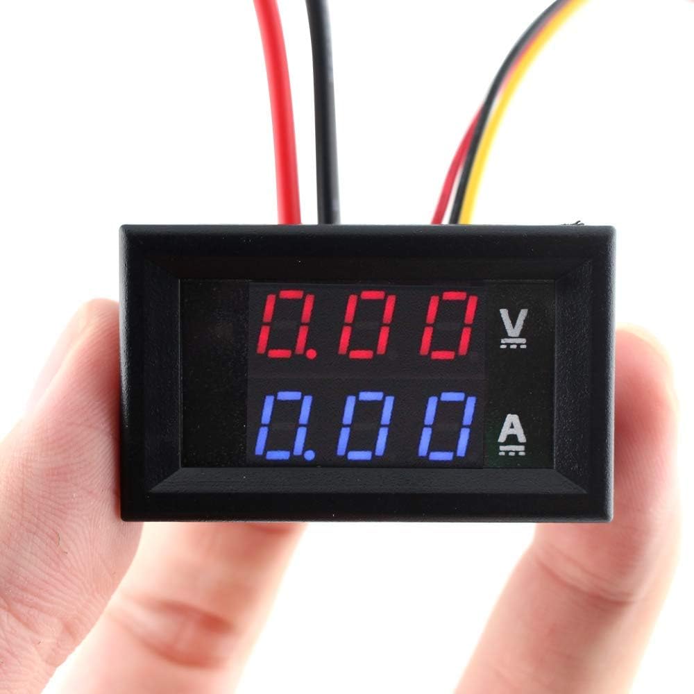
- Digital voltmeter + ammeter reads out supplied voltage and current
- System outputs power to barrel jacks
Repeat steps 2 through 4 for each additional channel of controlled power one would like in the box. For this project, I chose to have two channels.

Conclusion
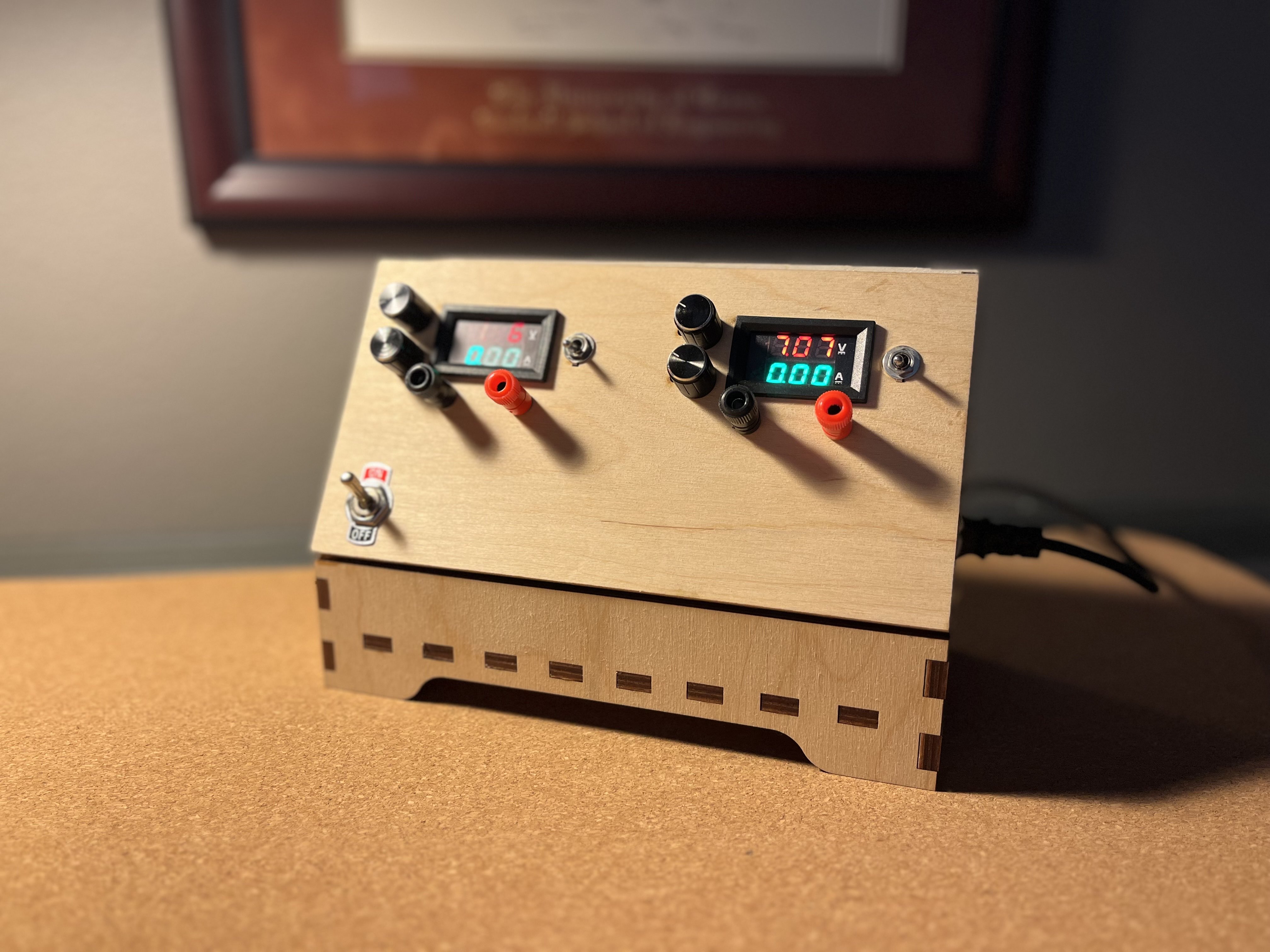
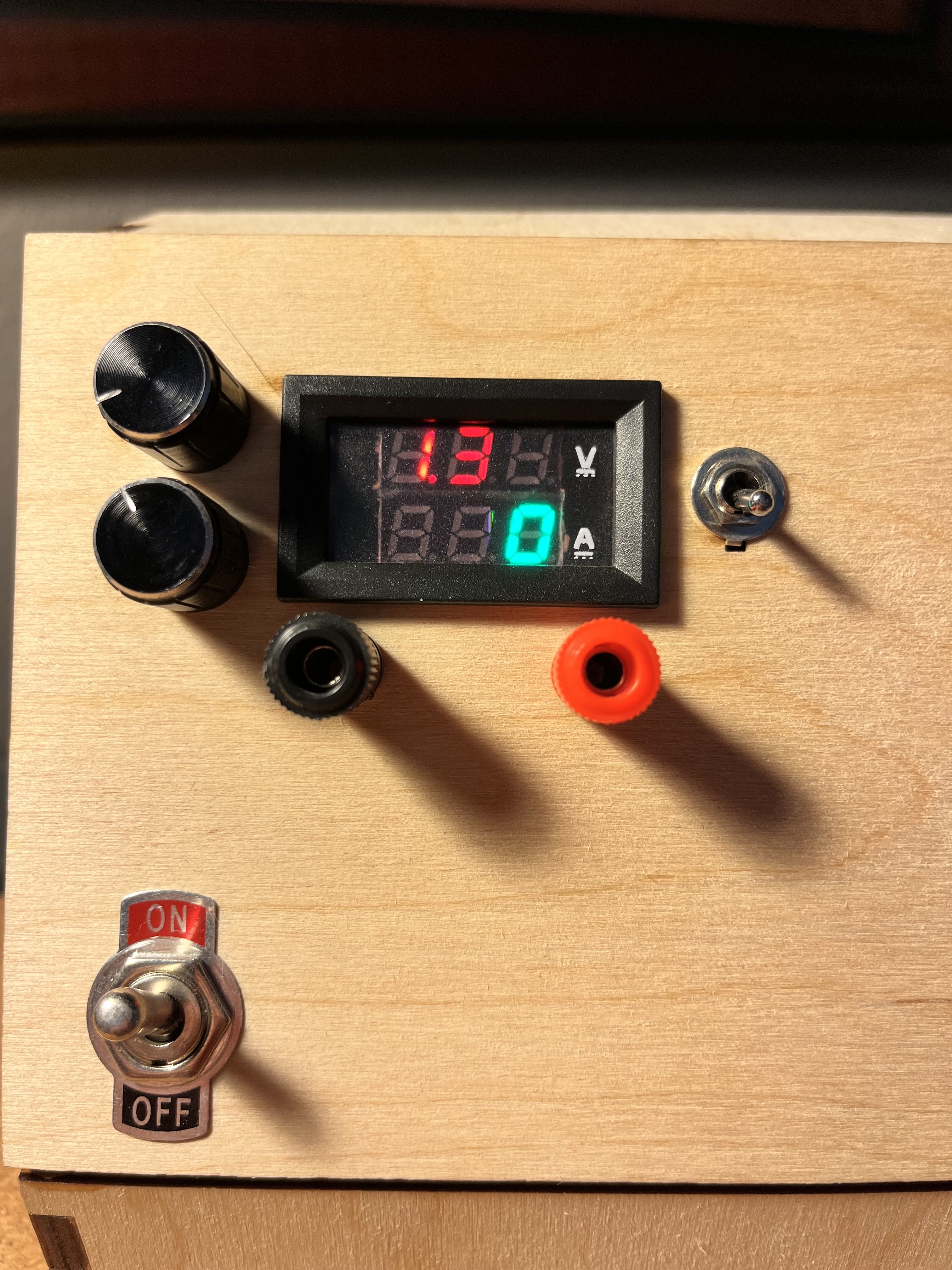
I love this project because it just works. I leveraged the excellent engineering of Apple to get a clean and reliable 30 volts, then used some very inexpensive parts to convert that into a power supply. Here a little engineering, some spare parts, and a laser cutter go a long way. If you ever were in need of a power supply for your own tinkering, I highly encourage this route.
